Philips Semiconductors
Preliminary specification
320 macrocell SRAM CPLD
PZ3320C/PZ3320N
During initialization and configuration, all I/O’s are 3-stated and the
internal weak pull-downs are active. See the section on terminations
for more information.
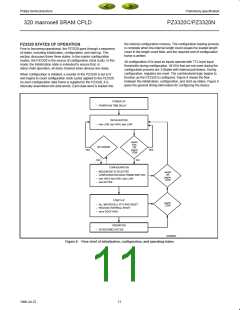
Initialization
Upon power-up, the device goes through an initialization process.
First, an internal power-on-reset circuit is triggered when power is
applied. When V reaches the voltage at which portions of the
DD
Start-up
PZ3320 begin to operate (1.5V), the configuration pins are set to be
inputs or outputs based on the configuration mode, as determined
by the mode select inputs M[2:0]. A time-out delay is initiated when
After configuration, the PZ3320 enters the start-up phase. This
phase is the transition between the configuration and operational
states. This transition occurs within three cclk cycles of the done pin
going high (it is acceptable to have additional cclk cycles beyond the
three required). The system design task in the start-up phase is to
ensure that multi-function pins (see pin function on page 34)
transition from configuration signals to user definable I/Os without
inadvertently activating devices in the system or causing bus
contention. The done signal goes high at the beginning of the start
up phase, which allows configuration sources to be disconnected so
that there is no bus contention when the I/Os become active. In
addition to controlling the PZ3320 during start-up, additional start-up
techniques to avoid contention include using isolation devices
between the PZ3320 and other circuits in the system, re-assigning
I/O locations, and keeping I/Os 3-stated until contentions are
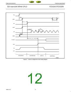
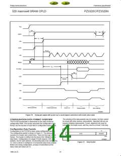
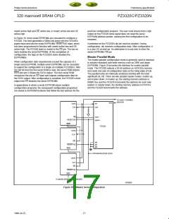
resolved. For example, Figure 10 shows how to use the global
tri-state (gts) signal to avoid signal contention when the mode select
pins (M3...M0) are used as I/O after configuration is finished.
Holding gts high until after the mode pins are disconnected from the
driving source allows pins M3 through M0 to transition from
configuration pins to user definable I/O without signal contention. In
V
reaches between 1.0V and 2.0V to allow the power supply
DD
voltage to stabilize. The initn and done outputs are low. At power-up,
if the power supply does not rise from 1.0V to V in less than
25ms, the user should delay configuration by inputting a low into
prgmn, initn, or resetn until V is greater than the recommended
DD
DD
minimum operating voltage (2.75V for commercial devices).
When initialization is complete, the active-low initialization signal
initn is released and must be pulled high by an external resistor. To
synchronize the configuration of multiple PZ3320s, one or more initn
pins should be wire-ANDed. If initn is held low by one or more
PZ3320s or an external device (the PZ3320 remains in the
initialization state), initn can be used to signal that the PZ3320s are
not yet initialized. After initn goes high for two internal clock cycles,
the mode select lines are sampled and the PZ3320 enters the
configuration state.
The High During Configuration (hdc), Low During Configuration
(ldcn), and done signals are active outputs in the PZ3320’s
initialization and configuration states. hdc, ldcn, and done can be
used to provide control of external logic signals such as reset, bus
enable, or EEPROM enable during configuration. For master parallel
configuration modes, these signals provide EEPROM enable control
and allow the data pins to be shared with user logic signals.
this case, the I/O become active a t
pulled low.
delay after the gts pin is
gtsr
The flip-flops are reset one cycle after done goes high so that
operation begins in a known state. The done outputs from multiple
PZ3320s can be wire ANDed and used as an active-high ready
signal, to disable PROMs with active-low enable(s), or to reset to
other parts of the system (see Figure 28).
If configuration has begun, an assertion of resetn or prgmn initiates
an abort, returning the PZ3320 to the initialization state. The resetn
and/or prgmn pins must be pulled back high before the PZ3320 will
enter the configuration state. During the start-up and operating
states, only the assertion of prgmn causes a re-configuration.
13
1998 Jul 22

 XILINX [ XILINX, INC ]