Philips Semiconductors
Preliminary specification
320 macrocell SRAM CPLD
PZ3320C/PZ3320N
cr_reg[1] <= cr_reg[0];
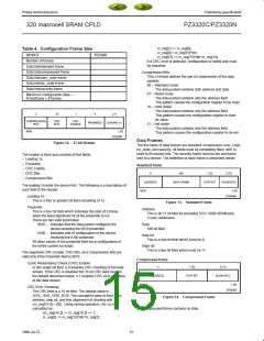
Table 4. Configuration Frame Size
cr_reg[0] < cr_reg[15]^din;
cr_reg[15] <= cr_reg[15]^din^cr_reg[14];
If a CRC error is detected, configuration is halted and must
be restarted.
DEVICE
PZ3320
Number of frames
Data bits/standard frame
Data bits/compressed frame
Data bits/user_code frame
Data bits/isc_code frame
Data bits/security frame
Compression Bits:
This 2-bit field defines the use of compression of the data
packets.
00 – Standard mode:
The data packet contains both address and data
01 – Reset mode:
Maximum configuration data—
The data packet contains only the address field.
This pattern causes the configuration register to be reset.
10 – Hold mode:
# bits/frame × # frames
The data packet contains only the address field.
This pattern causes the configuration register to hold
its value.
2
16
1
4
w4
COMPRESSION
BITS
CRC
BITS
CRC
ENABLE
PREAMBLE
LEADING 1s
11 – Set mode:
The data packet contains only the address field.
This pattern causes the configuration register to be set.
MSB
LSB
SP00594
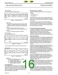
Data Frames
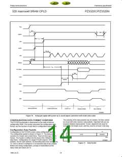
Figure 12. 27-bit Header
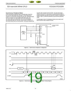
The five types of data frames are standard, compressed, user_code,
isc_code, and security. All fields must be completely filled, with 1s
used to fill unused bits. The security frame must be the last frame
sent to a device. The definition of each frame is described below:
The header is fixed and consists of five fields:
– Leading 1s,
– Preamble,
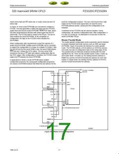
Standard frame
– CRC Enable,
11
546
1 (0)
2 (11)
– CRC Bits,
– Compression Bits.
ADDRESS
DATA FRAME
STOP BIT
ALIGN BITS
The leading 1s enter the device first. The following is a description of
each field in the header.
MSB
LSB
SP00595
Leading 1s:
This is a four or greater bit field consisting of 1s.
Figure 13. Standard Frame
Preamble:
Address:
This is a four bit field which indicates the start of a frame
when the least significant bit of the preamble is a 0.
There are two valid preambles:
This is an 11 bit filed for providing 1011 (1008 SRAM plus
3 user) addresses.
0010 – indicates that the data packet configures the
device receiving the 0010 preamble)
Data:
546 bit field.
0100 – indicates end of configuration of the device
receiving the 0100 preamble
All other values of the preamble field force configuration of
the entire system to restart.
Stop bit:
This is a one bit field which must be 0.
Align bit:
This is a two bit field which must be 11.
The segments CRC Enable, CRC Bits, and Compression Bits are
valid only if the Preamble field is 0010.
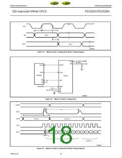
Compressed frame
Cyclic Redundancy Check (CRC) Enable:
11
1 (0)
2 (11)
In this single bit field, a 0 disables CRC checking of the data
stream. If the CRC is disabled the 16 bit CRC field must be
the default described below. A 1 enables CRC error checking
of the data stream.
ADDRESS
STOP BIT
ALIGN BITS
MSB
LSB
SP00597
CRC Error Checking:
The CRC field is a 16 bit field. The default value is
1010_1010_1010_1010. The calculated value is from data,
address, stop bit, and first alignment bit (starting with
crc_reg[15:0] = [0]). Using verilog operators, the crc is
calculated as:
Figure 14. Compressed Frame
The compressed frame contains no data.
crc_reg[14:2] <= cr_reg[14:2] << 1;
cr_reg[2] <= cr_reg[15]^din^cr_reg[1];
15
1998 Jul 22

 XILINX [ XILINX, INC ]