Philips Semiconductors
Preliminary specification
320 macrocell SRAM CPLD
PZ3320C/PZ3320N
V
DD
t
pord
t
PW
prgmn
t
IL
initn
resetn
t
init_clk
cclk
t
smode
M[3:0]
t
CL
I/O active
t
gtsr
GTS
done
hdc
t
HMODE
ldcn
INITIALIZATION
CONFIGURATION
START UP
OPERATIONAL
(RE-CONFIG)
SP00653
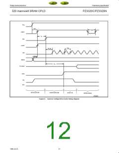
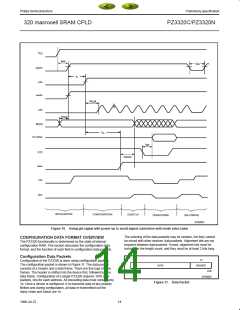
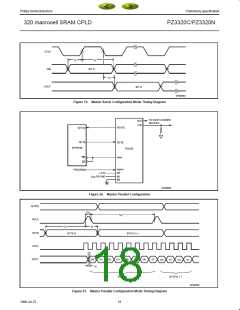
Figure 10. Using gts signal with power up to avoid signal contention with mode select pins
The ordering of the data packets may be random, but they cannot
be mixed with other devices’ data packets. Alignment bits are not
required between data packets. If used, alignment bits must be
included in the length count, and they must be at least 2 bits long.
CONFIGURATION DATA FORMAT OVERVIEW
The PZ3320 functionality is determined by the state of internal
configuration RAM. This section discusses the configuration data
format, and the function of each field in configuration data packets.
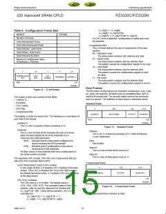
Configuration Data Packets
27
Configuration of the PZ3320 is done using configuration packets.
The configuration packet is shown in Figure 11. The data packet
consists of a header and a data frame. There are five type of data
frames. The header is shifted into the device first, followed by one
data frame. Configuration of a single PZ3320 requires 1010 data
packets, one for each address. All preceding data must contain only
1s. Once a device is configured, it re-transmits data of any polarity.
Before and during configuration, all data re-transmitted out the
daisy-chain port (dout) are 1s.
DATA
HEADER
MSB
LSB
SP00593
Figure 11. Data Packet
14
1998 Jul 22

 XILINX [ XILINX, INC ]