Spartan-6 FPGA Data Sheet: DC and Switching Characteristics
Input/Output Delay Switching Characteristics
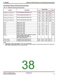
Table 38: IODELAY2 Switching Characteristics
Speed Grade
Symbol
Description
Units
-4
-3
-2
-1L
TIODCCK_CAL / TIODCKC_CAL
CAL pin Setup/Hold with respect to CK
CE pin Setup/Hold with respect to CK
INC pin Setup/Hold with respect to CK
RST pin Setup/Hold with respect to CK
0.28
–0.13
0.33
–0.13
0.48
–0.13
0.57
–0.24
ns
T
T
T
IODCCK_CE / TIODCKC_CE
IODCCK_INC/ TIODCKC_INC
0.14
–0.03
0.17
–0.03
0.25
–0.02
0.33
0.01
ns
ns
ns
0.10
0.02
0.12
0.03
0.18
0.06
0.23
0.11
IODCCK_RST/ TIODCKC_RST
0.12
–0.02
0.15
–0.02
0.22
–0.01
0.28
0.02
(2)
TTAP1
TTAP2
TTAP3
TTAP4
TTAP5
TTAP6
TTAP7
TTAP8
FMINCAL
Maximum tap 1 delay
Maximum tap 2 delay
Maximum tap 3 delay
Maximum tap 4 delay
Maximum tap 5 delay
Maximum tap 6 delay
Maximum tap 7 delay
Maximum tap 8 delay
8
14
16
ps
ps
40
66
77
95
120
141
194
249
276
341
188
140
166
231
292
343
424
188
ps
108
171
207
212
292
188
ps
ps
ps
ps
ps
Minimum allowed bit rate for calibration in variable
mode: VARIABLE_FROM_ZERO,
Mb/s
VARIABLE_FROM_HALF_MAX, and
DIFF_PHASE_DETECTOR.
TIODDO_IDATAIN
TIODDO_ODATAIN
Propagation delay through IODELAY2
Propagation delay through IODELAY2
Note 1 Note 1 Note 1 Note 1
Note 1 Note 1 Note 1 Note 1
Notes:
1. Delay depends on IODELAY2 tap setting. See TRACE report for actual values.
2. Maximum delay = integer (number of taps/8) × T + T (where n equals the remainder). For minimum delay consult the TRACE setup and hold
TAP8
TAPn
report. Minimum delay is greater than 30% of the maximum delay.
DS162 (v1.9) August 23, 2010
www.xilinx.com
Advance Product Specification
38

 XILINX [ XILINX, INC ]