Production Data
WM8352
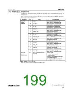
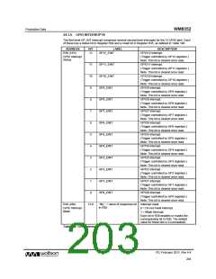
24.2 FIRST-LEVEL INTERRUPTS
Each first level interrupt has a status bit in Register R24, which can be read to determine the origin of
an IRQ event.
Each of these bits may be masked by setting the corresponding field in Register R32. By default, the
first-level interrupts are all masked.
ADDRESS
BIT
LABEL
DESCRIPTION
First-level over-current interrupt.
Note: This bit is cleared once read.
First-level under-voltage interrupt.
Note: This bit is cleared once read.
First-level current sink interrupt.
Note: This bit is cleared once read.
First-level external interrupt.
Note: This bit is cleared once read.
First-level codec interrupt.
R24 (18h)
13
OC_INT
UV_INT
CS_INT
EXT_INT
System
Interrupts
12
9
8
7
CODEC_INT
GP_INT
Note: This bit is cleared once read.
First-level GPIO interrupt.
6
Note: This bit is cleared once read.
First-level AUXADC comparator interrupt.
Note: This bit is cleared once read.
First-level RTC interrupt.
5
AUXADC_INT
RTC_INT
4
Note: This bit is cleared once read.
First-level system interrupt.
3
SYS_INT
Note: This bit is cleared once read.
First-level charger interrupt.
2
CHG_INT
USB_INT
Note: This bit is cleared once read.
First-level USB interrupt.
1
Note: This bit is cleared once read.
First-level wakeup interrupt.
0
WKUP_INT
Note: This bit is cleared once read.
Interrupt mask.
R32 (20h)
13:0
“IM_” + name of respective
bit in R25
System
0 = Do not mask interrupt.
Interrupt Mask
1 = Mask interrupt.
Each bit in R32 enables or masks the
corresponding bit in R24.
The default value for these bits is 1
(masked)
Note: Register is R24 is read-only.
Table 142 First Level Interrupt Status and Mask Bits
PD, February 2011, Rev 4.4
199
w

 WOLFSON [ WOLFSON MICROELECTRONICS PLC ]