WM8352
Production Data
23 WATCHDOG TIMER
The WM8352 includes a watchdog timer designed to detect a possible software fault condition where
the host processor has locked up. The watchdog timer checks for any write operation to the
watchdog control register R4 (04h) or receipt of a heartbeat signal from the host processor on GPIO9
(see Section 20). If neither event occurs within a programmable time, this is interpreted as a fault in
the host processor. The watchdog timer then raises an interrupt and/or generates a system reset; the
desired response to a watchdog timeout is set using the WDOG_MODE register field.
If GPIO9 is configured as HEARTBEAT input (GP9_FN = 0001, GP9_DIR = 1), then the Watchdog
Timer can only be reset by a rising logic level applied to the GPIO9 pin.
If GPIO9 is not configured as HEARTBEAT input, then the Watchdog Timer can only be reset by a
write operation to the watchdog control register R4 (04h).
If a System reset is triggered by the watchdog timeout, the WM8352 asserts the /RST pin and the
/RST and /MEMRST (GPIO) reset signals, resets the internal control registers and then initiates a
start-up sequence.
The watchdog timer can be halted for debug purposes using the WDOG_DEBUG bit. The watchdog
can be disabled in Hibernate mode using the WDOG_HIB_MODE bit. The watchdog timer duration is
set using WDOG_TO, as described in Table 139.
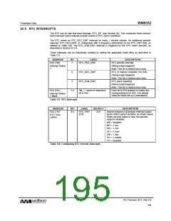
The Watchdog timeout interrupt event is indicated by the SYS_WDOG_TO_EINT register field. This
is one of the second-level interrupts which triggers a first-level System Interrupt, SYS_INT (see
Section 24). This can be masked by setting the mask bit as described in Table 140.
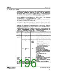
ADDRESS
BIT
LABEL
DEFAULT
DESCRIPTION
Halts watchdog timer for system debugging
0 = normal operation
R3 (03h)
7
WDOG_DEBU
G
0
System
control 1
1 = WDOG halt
R4 (04h)
7
WDOG_HIB_M
ODE
0
Watchdog behaviour in HIBERNATE state
0 = WDOG disabled in Hibernate
System
control 2
1 = WDOG controlled by WDOG_MODE in
Hibernate
5:4
WDOG_MODE
[2:0]
Dependan
t on
Watchdog mode
00 = Disabled
CONFIG
settings
01 = SYS_WDOG_TO interrupt on time-out
10 = WKUP_WDOG_RST interrupt and
System reset on time-out
11 = SYS_WDOG_TO interrupt on first time-
out, WKUP_WDOG_RST interrupt and
System reset on second time-out.
Protected by security key.
2:0
WDOG_TO
[2:0]
101
Watchdog timeout (seconds)
The timer is reset to this value when a
HEARTBEAT signal edge is detected or the
host writes to the watchdog control register.
000 = 0.125s
… (time doubles with each step)
101 = 4s
11x = Reserved
Protected by security key.
Watchdog behaviour in HIBERNATE state
0 = WDOG disabled in Hibernate
R5 (05h)
7
WDOG_HIB_M
ODE
0
System
Hibernate
1 = WDOG controlled by WDOG_MODE in
Hibernate
Note: WDOG_HIB_MODE can be accessed through R4 or through R5. Reading from or writing to
either register location has the same effect.
Table 139 Controlling the Watchdog Timer
PD, February 2011, Rev 4.4
196
w

 WOLFSON [ WOLFSON MICROELECTRONICS PLC ]