Production Data
WM8352
22.5 RTC INTERRUPTS
The RTC has its own first-level interrupt, RTC_INT (see Section 24). This comprises three second-
level interrupts which indicate periodic events or RTC Alarm conditions.
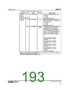
The RTC raises an RTC_SEC_EINT interrupt on every 1 second rollover. An additional periodic
interrupt, RTC_PER_EINT, is configurable with a frequency determined by the RTC_PINT field, as
defined in Table 138. The RTC_ALM_EINT interrupt is triggered by the RTC Alarm function, as
described in Section 22.2.4.
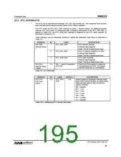
These interrupts can be individually masked by setting the applicable mask bit(s) as described in
Table 137.
ADDRESS
BIT
LABEL
DESCRIPTION
RTC periodic interrupt.
R25 (19h)
7
RTC_PER_EINT
Interrupt Status
1
(Rising Edge triggered)
Note: This bit is cleared once read.
RTC 1s rollover complete (1Hz tick).
(Rising Edge triggered)
6
5
RTC_SEC_EINT
RTC_ALM_EINT
Note: This bit is cleared once read.
RTC alarm signalled.
(Rising Edge triggered)
Note: This bit is cleared once read.
R33 (21h)
7:5
“IM_” + name of respective
bit in R25
Each bit in R33 enables or masks the
corresponding bit in R25. The default
value for these bits is 0 (unmasked).
Interrupt Status
1 Mask
Table 137 RTC Interrupts
ADDRESS
BIT
LABEL
DEFAULT
DESCRIPTION
R23 (17h)
6:4
RTC_PINT
[2:0]
010
Selects frequency of periodic interrupt output
pulse (32kHz period duration) as shown below.
When set time status is high, the periodic
output is disabled.
RTC Time
control
000 = disabled
001 = 1 sec
010 = 1 min
011 = 1 hour
100 = 1 day
101 = 1 month
11x = disabled
Table 138 Configuring RTC Periodic Interrupts
PD, February 2011, Rev 4.4
195
w

 WOLFSON [ WOLFSON MICROELECTRONICS PLC ]