WM8352
Production Data
24 INTERRUPT CONTROLLER
The WM8352 can send an interrupt signal to the host processor though the IRQ pin. Interrupts can
alert the host to a wide range of events and fault conditions. Each of these can be individually
enabled or masked. After receiving an interrupt, the host processor can read the interrupt registers in
order to determine what caused the interrupt, and take appropriate action if required.
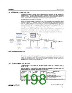
The WM8352 interrupt controller has two levels:
Second-level interrupts indicate a single event in one of the circuit blocks. This is indicated by setting
a register bit. This bit is a “sticky” bit - once it is set, it remains at logic 1 until the host processor
reads the register. When the processor reads the register, the interrupt bits in that register are
cleared. First-level interrupts are the logical OR of several second-level interrupts (usually all the
interrupts associated with one particular circuit block). The default polarity of IRQ is active low,
meaning that the IRQ signal is the logical NOR of all first-level interrupts.
Individual second-level interrupt bits can be masked, which prevents them from setting the First-level
interrupt. (Note that the “sticky” bit will be set as normal, even if that interrupt is masked.)
Individual first-level interrupts can also be masked, preventing them from asserting the IRQ output.
Figure 80 Interrupt Equivalent Logic
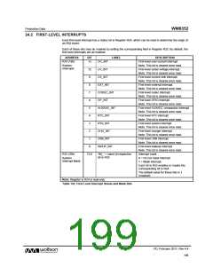
To find the cause of an interrupt signal, the host processor should first read the first-level interrupt
register R24 to locate the circuit blocks(s) where the interrupt originated; after that, the precise
cause(s) of the interrupt can be determined by reading the second-level interrupt register(s) as
appropriate to the indicated first-level interrupt event.
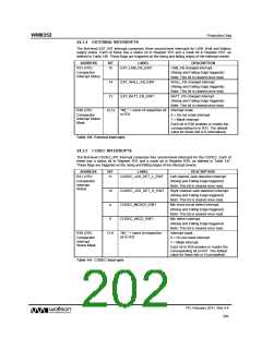
24.1 CONFIGURING THE IRQ PIN
The default polarity of IRQ is active low; this can be changed to active high if desired, by writing to
the IRQ_POL bit.
When the WM8352 is in the HIBERNATE state, interrupts can be disabled or can remain active. The
desired behaviour can be selected using the IRQ_HIB_MODE bit.
ADDRESS
R3 (03h)
BIT
LABEL
DEFAULT
DESCRIPTION
IRQ pin polarity
0
IRQ_POL
0
System
0 = active low (/IRQ)
Control 1
1 = active high (IRQ)
R5 (05h)
3
IRQ_HIB_MOD
E
0
IRQ pin state in hibernate mode
0 = Normal operation
System
Hibernate
1 = Forced to indicate there is no IRQ.
Table 141 Interrupts in HIBERNATE State
PD, February 2011, Rev 4.4
198
w

 WOLFSON [ WOLFSON MICROELECTRONICS PLC ]