Production Data
WM8352
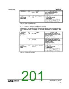
ADDRESS
BIT
LABEL
UV_DC1_EINT
DESCRIPTION
0
DCDC1 Under-voltage interrupt.
(Rising Edge triggered)
Note: This bit is cleared once read.
R36 (24h)
11:0
“IM_” + name of respective bit Interrupt mask.
in R28
Under Voltage
Interrupt Mask
0 = Do not mask interrupt.
1 = Mask interrupt.
Each bit in R36 enables or masks the
corresponding bit in R28. The default
value for these bits is 0 (unmasked).
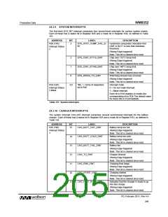
Table 144 Under-Voltage Interrupts
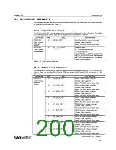
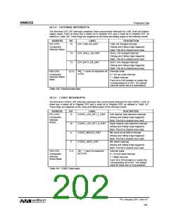
24.3.3 CURRENT SINK (LED DRIVER) INTERRUPTS
The first-level CS_INT interrupt comprises two second-level interrupts for the Current Sink functions.
Each of these has a status bit in Register R26 and a mask bit in Register R34, as defined in Table
145.
ADDRESS
BIT
LABEL
DESCRIPTION
R26 (1Ah)
13
CS1_EINT
CS2_EINT
Flag to indicate drain voltage can no
longer be regulated and output current
may be out of spec.
Interrupt Status
2
(Rising Edge triggered)
Note: This bit is cleared once read.
12
Flag to indicate drain voltage can no
longer be regulated and output current
may be out of spec.
(Rising Edge triggered)
Note: This bit is cleared once read.
Interrupt mask.
R34 (22h)
13:12
“IM_” + name of respective
bit in R26
Interrupt Status
2 Mask
0 = Do not mask interrupt.
1 = Mask interrupt.
Each bit in R34 enables or masks the
corresponding bit in R26. The default
value for these bits is 0 (unmasked).
Table 145 Current Sink Interrupts
PD, February 2011, Rev 4.4
201
w

 WOLFSON [ WOLFSON MICROELECTRONICS PLC ]