W90N745CD/W90N745CDG
Continued.
BITS
DESCRIPTIONS
Transmitter Holding Register Empty
0 = THR is not empty.
1 = THR is empty.
[5]
[4]
THRE
THRE is set when the last data word of TX FIFO is transferred to
Transmitter Shift Register (TSR). The CPU resets this bit when the THR
(or TX FIFO) is loaded. This bit also causes the UART to issue an interrupt
(Irpt_THRE) to the CPU when IER [1]=1.
Break Interrupt Indicator
This bit is set to a logic 1 whenever the received data input is held in the
"spacing state" (logic 0) for longer than a full word transmission time (that
is, the total time of "start bit" + data bits + parity + stop bits) and is reset
whenever the CPU reads the contents of the LSR.
BII
Framing Error Indicator
This bit is set to logic 1 whenever the received character does not have a
valid "stop bit" (that is, the stop bit following the last data bit or parity bit is
detected as a logic 0), and is reset whenever the CPU reads the contents
of the LSR.
[3]
[2]
FEI
PEI
Parity Error Indicator
This bit is set to logic 1 whenever the received character does not have a
valid "parity bit", and is reset whenever the CPU reads the contents of the
LSR.
Overrun Error Indicator
An overrun error will occur only after the RX FIFO is full and the next
character has been completely received in the shift register. The character
in the shift register is overwritten, but it is not transferred to the RX FIFO.
OE is indicated to the CPU as soon as it happens and is reset whenever
the CPU reads the contents of the LSR.
[1]
[0]
OEI
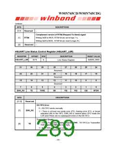
RX FIFO Data Ready
RFDR
0 = RX FIFO is empty
1 = RX FIFO contains at least 1 received data word.
LSR [4:2] (BII, FEI, PEI) are revealed to the CPU when its associated character is at the top of the RX
FIFO. These three error indicators are reset whenever the CPU reads the contents of the LSR.
LSR [4:1] (BII, FEI, PEI, OEI) are the error conditions that produce a "receiver line status interrupt"
(Irpt_RLS) when IER [2]=1. Reading LSR clears Irpt_RLS. Writing LSR is a null operation (not
suggested).
Publication Release Date: September 22, 2006
- 285 -
Revision A2

 WINBOND [ WINBOND ]