UCC28951
www.ti.com.cn
ZHCSIQ7A –AUGUST 2018 –REVISED DECEMBER 2021
1000
900
800
700
600
500
400
300
200
100
0
25
5
15
35 45 55 65 75 85 95 105 115 125
RT - Resistor - kΩ
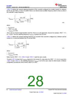
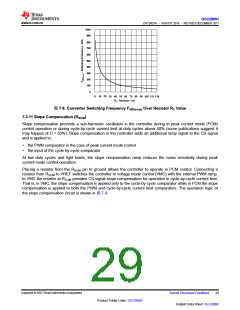
图7-8. Converter Switching Frequency FSW(nom) Over Resistor RT Value
7.3.11 Slope Compensation (RSUM
)
Slope compensation prevents a sub-harmonic oscillation in the controller during in peak current mode (PCM)
control operation or during cycle-by-cycle current limit at duty cycles above 50% (some publications suggest it
may happen at D < 50%). Slope compensation in the controller adds an additional ramp signal to the CS signal
and is applied to:
• the PWM comparator in the case of peak current mode control
• the input of the cycle-by-cycle comparator
At low duty cycles and light loads, the slope compensation ramp reduces the noise sensitivity during peak
current mode control operation.
Placing a resistor from the RSUM pin to ground allows the controller to operate in PCM control. Connecting a
resistor from RSUM to VREF switches the controller to voltage mode control (VMC) with the internal PWM ramp.
In VMC the resistor at RSUM provides CS signal slope compensation for operation in cycle-by-cycle current limit.
That is, in VMC, the slope compensation is applied only to the cycle-by-cycle comparator while in PCM the slope
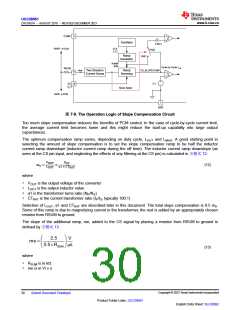
compensation is applied to both the PWM and cycle-by-cycle current limit comparators. The operation logic of
the slope compensation circuit is shown in 图7-9.
Copyright © 2023 Texas Instruments Incorporated
Submit Document Feedback
29
Product Folder Links: UCC28951
English Data Sheet: SLUSDB2

 TI [ TEXAS INSTRUMENTS ]