UCC28951
www.ti.com.cn
ZHCSIQ7A –AUGUST 2018 –REVISED DECEMBER 2021
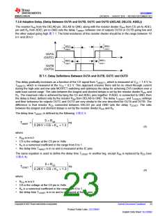
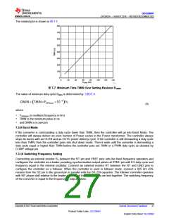
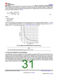
The related plot is shown in 图7-7.
800
700
600
500
400
300
200
100
0
0
20
40
60
80
100
120
140
RTMIN (kW)
D001
图7-7. Minimum Time TMIN Over Setting Resistor RTMIN
The value of minimum duty cycle DMIN is determined by 方程式9.
DMIN = TMIN´FSW(osc) ´10-4
%
(
)
(9)
where
• FSW(osc) is oscillator frequency in kHz
• TMIN is the minimum pulse in ns
• and DMIN is in percent
7.3.9 Burst Mode
If the converter is commanding a duty cycle lower than TMIN, then the controller will go into Burst Mode. The
controller will always deliver an even number of Power cycles to the Power transformer. The controller always
stops its bursts with an OUTB and an OUTC power delivery cycle. If the controller is still demanding a duty cycle
less than TMIN, then the controller goes into shut down mode. Then it waits until the converter is demanding a
duty cycle equal or higher than TMIN before the controller puts out TMIN or a PWM duty cycle as dictated by
COMP voltage pin.
7.3.10 Switching Frequency Setting
Connecting an external resistor RT between the RT pin and VREF pins sets the fixed frequency operation and
configures the controller as a leader providing synchronization output pulses at SYNC pin with 0.5 duty cycle and
frequency equal to the internal oscillator. Connect an external resistor RT between the RT and GND pins to
configure the controller as a follower. When the controller is used in follower mode, connect a 825 kΩ ±5%
resistor from the SS pin to the ground pin in parallel with the SS_EN capacitor. The follower controller operates
with 90° phase shift relative to the leader converter if their SYNC pins are tied together. The switching frequency
of the converter is equal to the frequency of output pulses.
Copyright © 2023 Texas Instruments Incorporated
Submit Document Feedback
27
Product Folder Links: UCC28951
English Data Sheet: SLUSDB2

 TI [ TEXAS INSTRUMENTS ]