UCC28951
www.ti.com.cn
ZHCSIQ7A –AUGUST 2018 –REVISED DECEMBER 2021
If the resistor from the RSUM pin is connected to the VREF pin, then the controller operates in voltage mode
control, still having the slope compensation ramp added to the CS signal used for cycle-by-cycle current limit. In
this case the slope is defined by 方程式14.
æ
ç
è
ö
÷
ø
(VREF - 2.5V)
0.5´RSUM
V
me =
ms
(14)
where
• VREF is in volts
• RSUM is in kΩ
• me is in V/μs
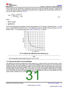
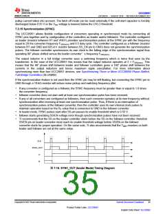
These are empirically derived equations without units agreement. As an example, substituting VREF = 5 V and
RSUM = 40 kΩ, yields the result 0.125 V/μs. The related plot of me as a function of RSUM is shown in 图 7-10,
Because VREF = 5 V, the plots generated from 方程式13 and 方程式14 coincide.
0.50
0.45
0.40
0.35
0.30
0.25
0.20
0.15
0.10
0.05
0
5
20 40 60 80 100 120 140 160 180 200
Rsum - Resistor - kΩ
图7-10. Slope of the Added Ramp Over Resistor RSUM
备注
The recommended resistor range for RSUM is 10 kΩto 1 MΩ.
7.3.12 Dynamic SR ON/OFF Control (DCM Mode)
The voltage at the DCM pin provided by the resistor divider RDCMHI between VREF pin and DCM, and RDCM from
DCM pin to GND, sets the percentage of 2-V current limit threshold for the Current Sense pin, (CS). If the CS pin
voltage falls below the DCM pin threshold voltage, then the controller initiates the light load power saving mode,
and shuts down the synchronous rectifiers, OUTE and OUTF. If the CS pin voltage is higher than the DCM pin
threshold voltage, then the controller runs in CCM mode. Connecting the DCM pin to VREF makes the controller
run in DCM mode and shuts both Outputs OUTE and OUTF. Shorting the DCM pin to GND disables the DCM
feature and the controller runs in CCM mode under all conditions.
Copyright © 2023 Texas Instruments Incorporated
Submit Document Feedback
31
Product Folder Links: UCC28951
English Data Sheet: SLUSDB2

 TI [ TEXAS INSTRUMENTS ]