UCC28951
www.ti.com.cn
ZHCSIQ7A –AUGUST 2018 –REVISED DECEMBER 2021
VREF
1
20 mA
RDCM(hi)
PWM
R = 77 kW
CS
DCM_COMP
+
2-Cycle
Counter
15
12
R = 77 kW
DCM
0 = DCM
1 = CCM
C = 6.5 pF
RDCM
C = 6.5 pF
Other Blocks
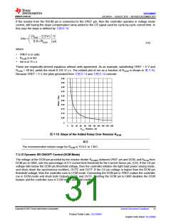
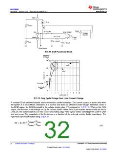
图7-11. DCM Functional Block
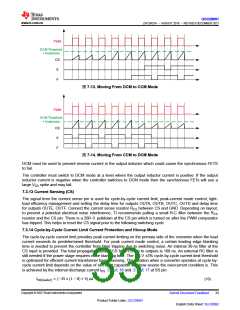
Moving into
DCM Mode
0.8
VS(max)
0.6
VS(min)
0.4
0.2
TMIN Setting
Burst Mode
Area
0
0
1
2
3
4
5
6
7
8
9
10
Load Current - A
图7-12. Duty Cycle Change Over Load Current Change
A nominal 20-µA switched current source is used to create hysteresis. The current source is active only when
the system is in DCM Mode. Otherwise, it is inactive and does not affect the node voltage. Therefore, when in
the DCM region, the DCM threshold is the voltage divider plus ΔV explained in 方程式 15. When in the CCM
region, the threshold is the voltage set by the resistor divider. When the CS pin reaches the threshold set on the
DCM pin, the system waits to see two consecutive falling edge PWM cycles before switching from CCM to DCM
and vice-versa. The magnitude of the hysteresis is a function of the external resistor divider impedance. The
hysteresis can be calculated using 方程式15:
RDCMHI ´RDCM
DV = 2´10-5
RDCMHI + RDCM
(15)
Copyright © 2023 Texas Instruments Incorporated
English Data Sheet: SLUSDB2
32
Submit Document Feedback
Product Folder Links: UCC28951

 TI [ TEXAS INSTRUMENTS ]