UCC28951
www.ti.com.cn
ZHCSIQ7A –AUGUST 2018 –REVISED DECEMBER 2021
方程式 10 defines the nominal switching frequency of the converter configured as a leader (resistor RT between
the RT pin and VREF). On the UCC28951 there is an internal clock oscillator frequency which is twice as that of
the controller's output frequency.
æ
ç
ç
ç
ö
÷
÷
÷
2.5´103
RT
VREF - 2.5V
F
=
kHz
SW(nom)
æ
ç
è
ö
÷
ø
kW
+1´
ç
÷
ç
÷
V
è
ø
(10)
where
• RT is in kΩ
• VREF is in volts
• FSW(nom) is in kHz
This is also an empirical approximation and thus, there is no unit agreement. Assume for example, VREF = 5 V,
RT = 65 kΩ. Then the switching frequency FSW(nom) is going to be 92.6 kHz.
方程式 11 defines the nominal switching frequency of converter if the converter configured as a follower and the
resistor RT is connected between the RT pin and GND.
æ
ç
ç
ç
ç
è
ö
÷
÷
÷
÷
ø
2.5´103
RT
F
=
kHz
SW(nom)
æ
ö
kW
+1´
ç
÷
2.5V
V
è
ø
(11)
where
• RT is in kΩ
• FSW(nom) is in kHz
Notice that for VREF = 5 V, 方程式10 and 方程式11 yield the same results.
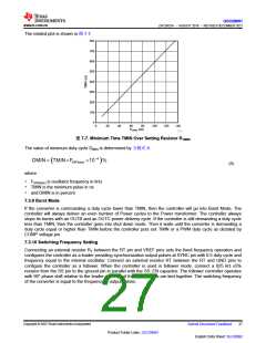
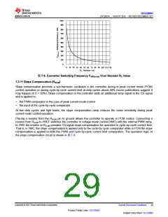
The plot in 图7-8 shows how FSW(nom) depends on the resistor RT value when the VREF = 5 V. As it is seen from
方程式 10 and 方程式 11, the switching frequency FSW(nom) is set to the same value for either leader or follower
configuration provided the same resistor value RT is used.
Copyright © 2023 Texas Instruments Incorporated
English Data Sheet: SLUSDB2
28
Submit Document Feedback
Product Folder Links: UCC28951

 TI [ TEXAS INSTRUMENTS ]