UCC21759-Q1
SLUSEB4A – AUGUST 2020 – REVISED DECEMBER 2020
www.ti.com
UCC217xx
In Module or
Discrete
VCC
VDD
13V to
33V
+
+
3V to 5.5V
APWM
œ
œ
AIN
+
DEMOD
MOD
µC
Rfilt
Cfilt
OSC
GND
COM
Thermal
Diode
NTC or
PTC
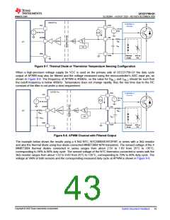
Figure 9-7. Thermal Diode or Thermistor Temperature Sensing Configuration
When a high-precision voltage supply for VCC is used on the primary side of UCC21759-Q1 the duty cycle
output of APWM may also be filtered and the voltage measured using the microcontroller's ADC input pin, as
shown in Figure 9-8. The frequency of APWM is 400kHz, so the value for Rfilt_2 and Cfilt_2 should be such that
the cutoff frequency is below 400kHz. Temperature does not change rapidly, thus the rise time due to the RC
constant of the filter is not under a strict requirement.
UCC217xx
VDD
In Module or
Discrete
VCC
13V to
33V
+
+
œ
3V to 5.5V
APWM
œ
AIN
+
DEMOD
MOD
µC
Rfilt_1
Rfilt_2
Cfilt_2
GND
OSC
Cfilt_1
COM
Thermal
Diode
NTC or
PTC
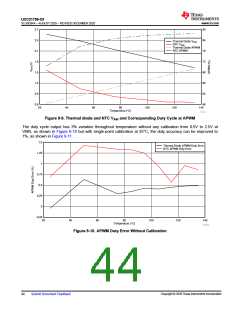
Figure 9-8. APWM Channel with Filtered Output
The example below shows the results using a 4.7kΩ NTC, NTCS0805E3472FMT, in series with a 3kΩ resistor
and also the thermal diode using four diode-connected MMBT3904 NPN transistors. The sensed voltage of the 4
MMBT3904 thermal diodes connected in series ranges from about 2.5V to 1.6V from 25°C to 135°C,
corresponding to 50% to 68% duty cycle. The sensed voltage of the NTC thermistor connected in series with the
3kΩ resistor ranges from about 1.5V to 0.6V from 25°C to 135°C, corresponding to 70% to 88% duty cycle. The
voltage at VAIN of both sensors and the corresponding measured duty cycle at APWM is shown in Figure 9-9.
Copyright © 2020 Texas Instruments Incorporated
Submit Document Feedback
43

 TI [ TEXAS INSTRUMENTS ]