UCC21759-Q1
SLUSEB4A – AUGUST 2020 – REVISED DECEMBER 2020
www.ti.com
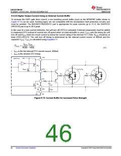
9.2.2.8 Higher Output Current Using an External Current Buffer
To increase the IGBT gate drive current, a non-inverting current buffer (such as the NPN/PNP buffer shown in
Figure 9-13) can be used. Inverting types are not compatible with the desaturation fault protection circuitry and
must be avoided. The MJD44H11/MJD45H11 pair is appropriate for peak currents up to 15 A, the D44VH10/
D45VH10 pair is up to 20 A peak.
In the case of a over-current detection, the soft turn off (STO) is activated. External components must be added
to implement STO instead of normal turn off speed when an external buffer is used. CSTO sets the timing for soft
turn off and RSTO limits the inrush current to below the current rating of the internal FET (10A). RSTO should be at
least (VDD-VEE)/10. The soft turn off timing is determined by the internal current source of 400mA and the
capacitor CSTO. CSTO is calculated using Equation 11.
ISTO ∂ tSTO
CSTO
=
(11)
•
•
ISTO is the the internal STO current source, 400mA
tSTO is the desired STO timing
VDD
VDD
UCC217xx
ROH
Cies=Cgc+Cge
OUTH
OUTL
RNMOS
Cgc
Cgc
RG_2
RG_1
RG_Int
RG_Int
Cge
Cge
ROL
CSTO
COM
VEE
RSTO
Figure 9-13. Current Buffer for Increased Drive Strength
Copyright © 2020 Texas Instruments Incorporated
46
Submit Document Feedback

 TI [ TEXAS INSTRUMENTS ]