TPS7H5005-SEP, TPS7H5006-SEP, TPS7H5007-SEP, TPS7H5008-SEP
SLVSGG1 – FEBRUARY 2022
www.ti.com
8.3.15 Hiccup Mode Operation (HICC)
Once the voltage at CS_ILIM exceeds 1.05 V, the device will execute cycle-by-cycle current limiting. The
controller output is turned on at the beginning of each cycle until such point that CS_ILIM voltage reaches the
current sense threshold VCS_ILIM, when the output is turned off. At the same time, each time the voltage at
CS_ILIM reaches 1.05 V, the capacitor at CHICC is charged via a 80-µA current (hiccup delay current). This
hiccup delay current is terminated at the end of the clock cycle. As long as there is still an overcurrent being
detected, the cycle-by-cycle limiting will continue until the voltage on CHICC reaches 0.6 V. This cycle-by-cycle
limiting period is referred to as the delay mode. As such, the capacitor CHICC can be chosen to dictate the
amount of time that the controller will spend in delay mode.
tdelay × 80 A
CHICC
=
0.6 V
(13)
Note that this equation is an approximation since:
•
depending on the system behavior and if CHICC has been charged previously, CHICC may not start at 0 V as
assumed by the equation
•
the 80-μA charging current is a pulsed current, the duration of which will be dictated by the nature of the
overcurrent and when the current sense threshold is reached during each clock cycle
After the voltage on HICC pin reaches 0.6 V, the SS pin of the controller is discharged and switching stops.
The voltage on HICC is then quickly pulled up to 1 V with the pull-up current limited to approximately 1 mA.
Once HICC voltage reaches 1 V, the 1-µA hiccup restart current begins to discharge CHICC. The controller will
not switch until HICC voltage falls to 0.3 V. Once the voltage falls to 0.3 V, the controller will initiate its soft-start
sequence again. If the overcurrent has disappeared, normal operation will resume. The hiccup time, which is the
entire non-switching period, can be calculated using Equation 14.
CHICC × (1 V 0.3 V)
tHICC
=
1 A
(14)
In summary, the capacitor CHICC on the HICC pin controls the amount of time the controller spends performing
cycle-by-cycle limiting before switching stops, and also controls the amount of time switching is disabled before
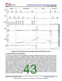
re-start is attempted again. It is recommended to use a minimum of 3.3 nF for CHICC. Figure 8-15 shows the
typical behavior during hiccup mode. Note that the OUTB and corresponding CS_ILIM waveforms are only
applicable for TPS7H5005-SEP and TPS7H5008-SEP.
Copyright © 2022 Texas Instruments Incorporated
42
Submit Document Feedback
Product Folder Links: TPS7H5005-SEP TPS7H5006-SEP TPS7H5007-SEP TPS7H5008-SEP

 TI [ TEXAS INSTRUMENTS ]