TPS7H5005-SEP, TPS7H5006-SEP, TPS7H5007-SEP, TPS7H5008-SEP
www.ti.com
SLVSGG1 – FEBRUARY 2022
NORMAL
OVERCURRENT
HICCUP
SOFT-START
OUTA
.
.
.
.
.
.
.
.
.
.
.
.
.
.
.
.
.
.
.
.
.
.
.
t
t
t
t
OUTB
.
.
.
.
.
1 V
CS_ILIM
.
. . . . . . . . . . . . .
1 mA
IHICC
75 µA
-1 µA
.
. . . . . . . . . . . . .
-1 mA
1 V
0.6 V
0.3 V
VHICC
t
t
3 V
SS
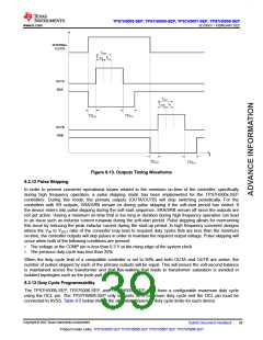
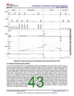
Figure 8-15. Cycle-by-Cycle Current Limit Delay Timer and Hiccup Restart Timer
8.3.16 External Fault Protection (FAULT)
The FAULT pin provides the user with flexibility to implement additional protections for the converter, such as
input overcurrent protection or overvoltage protection, if desired. This pin can also be utilized in the event that
the user desires more stringent protections than what is offered by the controller (i.e. thermal shutdown). The
user can design external logic circuitry to generate the signal necessary to drive this pin based on the protection
function. If the voltage on the FAULT pin exceeds 0.6 V (typical) for a duration specified by the FAULT minimum
pulse width, a fault shutdown will occur. This FAULT minimum pulse width duration, which is between 0.4 µs
and 1.4 µs, is intended to prevent any spurious triggering due to short-term transients. Since any short-term
transient event detected on this pin that is less than 1.4 µs in duration may not activate the FAULT pin, these
events should be properly evaluated by the user in order to determine the impact to the overall system. Once the
fault is detected, the SS pin is discharged and the controller outputs stop switching and stay low as long as the
rising threshold is exceeded on the pin. Once the fault has subsided and the voltage of FAULT falls below the
falling threshold of 0.5 V (typical), the TPS7H500x-SEP enters a delay period that is dependent on the switching
frequency. This delay is appoximately equal to 15 switching frequency cycles in addition to an internal logic
delay. The soft-start sequence is again initiated after the delay period has finished. Equation 15 can be used to
determine the length of the fault delay.
Copyright © 2022 Texas Instruments Incorporated
Submit Document Feedback
43
Product Folder Links: TPS7H5005-SEP TPS7H5006-SEP TPS7H5007-SEP TPS7H5008-SEP

 TI [ TEXAS INSTRUMENTS ]