TPS7H5005-SEP, TPS7H5006-SEP, TPS7H5007-SEP, TPS7H5008-SEP
SLVSGG1 – FEBRUARY 2022
www.ti.com
Table 8-5. Allowable Duty Cycle Limits for
TPS7H500x-SEP
DEVICE
DUTY CYCLE LIMIT OPTIONS
50%, 75%, 100%
75%, 100%
TPS7H5005-SEP
TPS7H5006-SEP
TPS7H5007-SEP
TPS7H5008-SEP
75%, 100%
50%
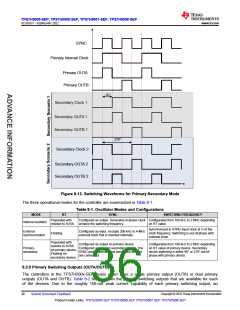
For applications in which 100% duty cycle is needed, the user should select one of the three compatible devices
and connect DCL to VLDO. For other applications which require a duty cycle limit restriction, the DCL pin could
be connected to AVSS for 50% duty cycle limit or left floating for 75% maximum duty cycle. Note that only
TPS7H5005-SEP and TPS7H5008-SEP support the 50% duty cycle limit (DCL = AVSS), and OUTB/SRB are
only active in this configuration. The 50% duty cycle limit case is intended to support applications such as the
push-pull that require two primary switching outputs, and in the case of the TPS7H5005-SEP, two synchronous
rectification outputs. If the controller is being operated in external synchronization mode, the most precise duty
cycle limiting results are obtained when the applied system clock has a 50% duty cycle. Specifically, for the case
when the duty cycle limit is set to 75% (DCL = floating) in the supported devices, there may be some variation of
the duty cycle limit that is dependent on the duty cycle of the external clock applied at SYNC
Table 8-6. DCL Pin Configurations
MAXIMUM DUTY CYCLE
DCL CONNECTION
(NOMINAL)
100%
75%
50%
VLDO
Floating
AVSS
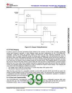
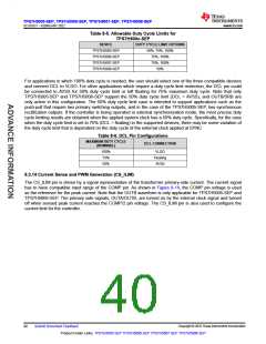
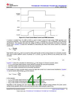
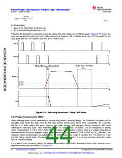
8.3.14 Current Sense and PWM Generation (CS_ILIM)
The CS_ILIM pin is driven by a signal representative of the transformer primary-side current. The current signal
has to have compatible input range of the COMP pin. As shown in Figure 8-14, the COMP pin voltage is used
as the reference for the peak current. Note that the OUTB waveform is only applicable for TPS7H5005-SEP and
TPS7H5008-SEP. The primary side signals, OUTA/OUTB, are turned on by the internal clock signal and turned
off when sensed peak current reaches the COMP/2 pin voltage. The CS_ILIM pin is also used to configure the
current limit for the controller.
Copyright © 2022 Texas Instruments Incorporated
40
Submit Document Feedback
Product Folder Links: TPS7H5005-SEP TPS7H5006-SEP TPS7H5007-SEP TPS7H5008-SEP

 TI [ TEXAS INSTRUMENTS ]