TPS7H5005-SEP, TPS7H5006-SEP, TPS7H5007-SEP, TPS7H5008-SEP
www.ti.com
SLVSGG1 – FEBRUARY 2022
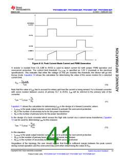
Figure 8-14. Peak Current Mode Control and PWM Generation
A resistor is needed from CS_ILIM to AVSS is used to detect current for both proper PWM operation and
overcurrent protection. The current limit threshold VCS_ILIM, is specified as 1.05 V (nominal) in the electrical
specifications. This indicates that when the voltage on this pin reaches this threshold, the device will go into
hiccup mode. Equation 10 shows the calculation for determining the value of the sense resistor for a selected
current limit.
VCS_ILIM
RCS
=
ILIM
(10)
Note that the value of ILIM has to account for where and how the current is being sensed. For a forward converter
with sense resistor between source of primary FET to AVSS, ILIM will be referred to the primary side of the
converter.
NS
ILIM = IL,PEAK
×
NP
(11)
Equation 11 shows the calculation for determining ILIM in the design of a forward converter, where:
•
•
•
IL,PEAK is the peak output inductor current desired to activate the overcurrent protection
NS is the number of secondary turns for the power transformer
NP is the number of primary turns for the power transformer
In the design of a buck converter which senses the high side current via a current sense transformer, Equation
12 can be used for determining ILIM for this instance.
NCSP
ILIM = IL,PEAK
×
NCSS
(12)
In this equation:
•
•
•
IL,PEAK is the peak output inductor current desired to activate the overcurrent protection
NCSP is the number of primary turns of the current sense transformer
NCSS is the number of secondary turns of the current sense transformer
Regardless of the topology, the user should ensure that there is sufficient margin between the peak current
during normal operation and the overcurrent trip point when determining the value of RCS
.
Copyright © 2022 Texas Instruments Incorporated
Submit Document Feedback
41
Product Folder Links: TPS7H5005-SEP TPS7H5006-SEP TPS7H5007-SEP TPS7H5008-SEP

 TI [ TEXAS INSTRUMENTS ]