TPS7H5005-SEP, TPS7H5006-SEP, TPS7H5007-SEP, TPS7H5008-SEP
www.ti.com
SLVSGG1 – FEBRUARY 2022
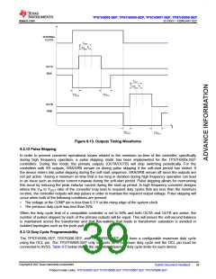
Figure 8-13. Outputs Timing Waveforms
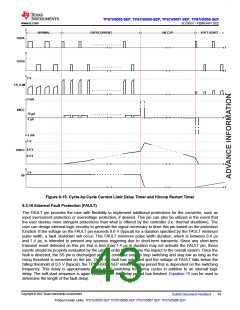
8.3.12 Pulse Skipping
In order to prevent converter operational issues related to the minimum on-time of the controller, specifically
during high frequency operation, a pulse skipping mode has been implemented for the TPS7H500x-SEP
controllers. During this mode, the primary outputs (OUTA/OUTB) will stop switching periodically. For the
controllers with SR outputs, SRA/SRB remain on during pulse skipping if the soft-start period has ended. If
the device enters into pulse skipping during the soft-start sequence, SRA/SRB remain off since the outputs are
not yet active. Having a minimum on-time that is too long in duration during high frequency operation can lead
to an issue such as inductor current runaway during the soft-start period. Pulse skipping allows for overcoming
this issue by reducing the peak inductor current during the start-up period. In high frequency converter designs
where the VIN to VOUT ratio of the converter may lead to required duty cycles that are less than the minimum
on-time, the controller outputs will skip pulses in order to maintain the required output voltage. Pulse skipping will
occur when both of the following conditions are present:
•
•
The voltage at the COMP pin is less than 0.3 V at the rising edge of the system clock
The previous duty cycle was less than 25%
When the duty cycle limit of a compatible controller is set to 50% and both OUTA and OUTB are active, the
number of pulses skipped by each of the primary outputs will be equal. This will ensure the volt-second balance
is maintained across the transformer and that flux-walking that leads to transformer saturation is avoided in
isolated topologies such as the push-pull.
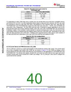
8.3.13 Duty Cycle Programmability
The TPS7H5005-SEP, TPS75006-SEP, and TPS7H5007-SEP each have a configurable maximum duty cycle
using the DCL pin. The TPS7H5008-SEP only supports 50% maximum duty cycle and the DCL pin must be
connected to AVSS. Table 8-5 below shows the allowable maximum duty cycle limits for each device.
Copyright © 2022 Texas Instruments Incorporated
Submit Document Feedback
39
Product Folder Links: TPS7H5005-SEP TPS7H5006-SEP TPS7H5007-SEP TPS7H5008-SEP

 TI [ TEXAS INSTRUMENTS ]