TPS7H5005-SEP, TPS7H5006-SEP, TPS7H5007-SEP, TPS7H5008-SEP
SLVSGG1 – FEBRUARY 2022
www.ti.com
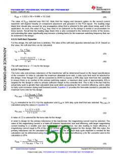
TPS7H500x-SEP
VOUT
Transconductance
Error Amplifier
RTOP
VSENSE
VREF
-
gmea
RBOTTOM
+
CO RO
Type 2A
Type 2B
Compensation
Compensation
COMP
RCOMP
RCOMP
CHF
CCOMP
CCOMP
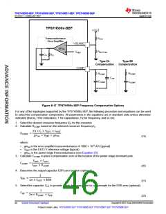
Figure 8-17. TPS7H500x-SEP Frequency Compensation Options
For any of the topologies supported by the TPS7H500x-SEP, the following procedure and equations can be used
to select the compensation components. All parameters in the equations are in standard units unless otherwise
indicated (that is, H for inductance, F for capacitance, Hz for frequency, and so on).
1. Select the desired crossover frequency (fc) for the converter.
2. Calculate RCOMP based on the selected crossover frequency fc.
2 × fc × VOUT × COUT
RCOMP
=
gmea × VREF × gmPS
(19)
where:
•
•
•
gmea is the error amplifier transconductance of 1800 × 10-6 A/V (typical)
VREF is the 0.613 V reference voltage (typical)
gmPS is the power stage transconductance (see Equation 23)
3. Calculate CCOMP to place compensation zero at the location of the power stage dominant pole.
VOUT × COUT
CCOMP
=
IOUT × RCOMP
(20)
(21)
4. Determine the output capacitor ESR zero location (optional).
1
fESR
=
2 × COUT × ESR
5. Select the capacitor CHF to provide a high frequency pole to compensate for the ESR zero (optional).
1
CHF
=
2 × RCOMP × fESR
(22)
Copyright © 2022 Texas Instruments Incorporated
46
Submit Document Feedback
Product Folder Links: TPS7H5005-SEP TPS7H5006-SEP TPS7H5007-SEP TPS7H5008-SEP

 TI [ TEXAS INSTRUMENTS ]