TPS7H5005-SEP, TPS7H5006-SEP, TPS7H5007-SEP, TPS7H5008-SEP
SLVSGG1 – FEBRUARY 2022
www.ti.com
14700
tdFLT
=
+ 2
fsw
(15)
In this equation:
•
•
tdFLT is the fault delay duration in μs
fsw is the switching frequency in kHz
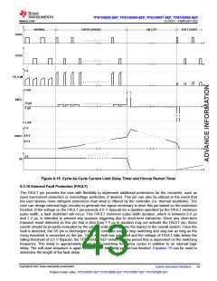
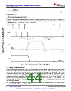
If the FAULT threshold is exceeded during the delay, the entire sequence is started again. Figure 8-16 shows the
switching waveforms when the fault mode has been activated in the controller. Note that OUTB waveforms are
only applicable for TPS7H5005-SEP and TPS7H5008-SEP.
Figure 8-16. Switching Waveforms During Fault Mode
8.3.17 Slope Compensation (RSC)
When utilizing peak current mode control in switching power converter design, the converter can enter into an
unstable state when the duty cycle for the main power switch rises above 50%. Essentially, the converter
will be in a state where the error between the peak current and average current increases with each
subsequent switching cycle. This instability, known as subharmonic oscillation, can be mitigated by adding
slope compensation. For the TPS7H500x-SEP, the slope compensation is in the form of a voltage ramp that is
subtracted from the error amplifier output divided down by the parameter CCSR (COMP to CS_LIM ratio). The
minimum slope compensation for stability over the entire duty cycle range is equal to 0.5 × m, where m is the
inductor falling current slope. The recommended slope compensation is 1 × m, as any increase above this value
will not improve stability.
For a typical buck converter, setting the slope compensation equal to the downward slope of the sensed current
waveform yields the calculation in Equation 16.
Copyright © 2022 Texas Instruments Incorporated
44
Submit Document Feedback
Product Folder Links: TPS7H5005-SEP TPS7H5006-SEP TPS7H5007-SEP TPS7H5008-SEP

 TI [ TEXAS INSTRUMENTS ]