TPS7H5005-SEP, TPS7H5006-SEP, TPS7H5007-SEP, TPS7H5008-SEP
www.ti.com
SC =
SLVSGG1 – FEBRUARY 2022
VOUT NCSP
×
× RCS
L
NCSS
(16)
where:
•
•
•
•
•
SC is the slope compensation value in V/μs
L is the output inductor value in μH
NCSP is the number of primary turns of the current sense transformer
NCSS is the number of secondary turns on the current sense transformer
RCS is the value of the current sense resistor in Ω
If no current sense transformer is used, set NCSP/NCSS to 1.
The slope compensation for the forward converter will be similar with the note that the sensed current waveform
would also need to take into account the turns ratio of the main power transformer.
VOUT NS NCSP
×
SC =
×
× RCS
L
NP NCSS
(17)
where:
•
•
NS is the number of secondary turns of the power transformer
NP is the number of primary turns of the power transformer
For the TPS7H500x-SEP controllers, a resistor from the RSC pin to AVSS can be used to set the desired slope
compensation of the controller. Equation 18 shows the calculation for determining the proper resistor value for
RSC.
28.3
SC1.1
RSC =
(18)
where:
•
•
SC is the desired slope compensation is V/μs
RSC is in kΩ
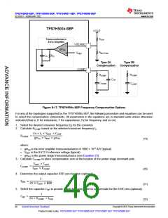
8.3.18 Frequency Compensation
Since the TPS7H500x-SEP uses a transconductance error amplifier (OTA), either Type 2A or Type 2B frequency
compensation can be applied. The primary difference between the two compensation schemes is that Type
2A has an additional capacitor CHF in parallel with RCOMP and CCOMP in order to provide high-frequency noise
attenuation. These components will be connected between the COMP pin of the controller, which is the OTA
output, and AVSS.
Copyright © 2022 Texas Instruments Incorporated
Submit Document Feedback
45
Product Folder Links: TPS7H5005-SEP TPS7H5006-SEP TPS7H5007-SEP TPS7H5008-SEP

 TI [ TEXAS INSTRUMENTS ]