TPS7H5005-SEP, TPS7H5006-SEP, TPS7H5007-SEP, TPS7H5008-SEP
SLVSGG1 – FEBRUARY 2022
www.ti.com
Outputs (SRA/SRB), the SR outputs will be disabled during soft start, so the dead time is observed only after this
sequence is complete.
After OUTA or OUTB goes high, a leading edge blank time is implemented to remove any transient noise
from the current sensing loop. While the leading edge blank time is fixed (50 ns typical) for TPS7H5007-SEP,
the leading edge blank time for all other devices in the TPS7H500x-SEP series is programmable by placing
an external resistor from LEB to AVSS. This pin cannot be left floating for the programmable devices and a
minimum resistor value of 10 kΩ is required from LEB to AVSS. The maximum resistor value that should be used
is 300 kΩ. The equation for determining the value of RLEB for a desired leading edge blank time is shown in
Equation 9.
RLEB = 1.212 × LEB 9.484
(9)
where:
•
•
LEB is the desired leading edge blank time in ns
RLEB is in kΩ
Table 8-4. Dead Time and Leading Edge Blank Time
Configurations for TPS7H500x-SEP
LEADING EDGE
BLANK TIME
DEVICE
DEAD TIME
Resistor
programmable
Resistor
programmable
TPS7H5005-SEP
Resistor
programmable
Resistor
programmable
TPS7H5006-SEP
TPS7H5007-SEP
TPS7H5008-SEP
Fixed (50-ns typical) Fixed (50-ns typical)
Resistor
Not applicable
programmable
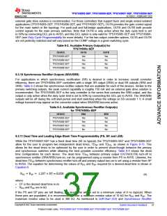
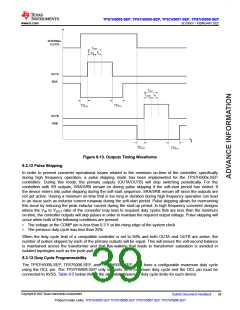
In Figure 8-13, the dead times and leading edge blank times are shown for the switching waveforms. This
figure also illustrates the minimum on-time of the device, which is comprised of the programmed blank time
TLEB and an internal logic delay td. Note that the dead-time waveforms for OUTB/SRB are only applicable for
TPS7H5005-SEP.
Copyright © 2022 Texas Instruments Incorporated
38
Submit Document Feedback
Product Folder Links: TPS7H5005-SEP TPS7H5006-SEP TPS7H5007-SEP TPS7H5008-SEP

 TI [ TEXAS INSTRUMENTS ]