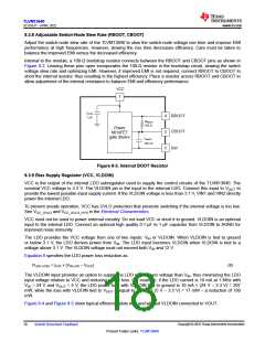
TLVM13640
SLVSGJ7 – APRIL 2022
www.ti.com
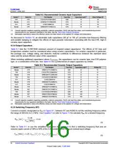
Table 8-2. Recommended Ceramic Input Capacitors
Vendor(1)
TDK
Dielectric
X7R
Part Number
Case Size
Capacitance (µF)(2)
Rated Voltage (V)
C3216X7R1H106K160AC
GCM32EC71H106KA03K
12105C106MAT2A
1206
10
10
10
10
50
50
50
50
Murata
AVX
X7S
1210
X7R
1210
Murata
X7R
GRM32ER71H106KA12L
1210
(1) Consult capacitor suppliers regarding availability, material composition, RoHS and lead-free status, and manufacturing process
requirements for any capacitors identified in this table. See the Third-Party Products Disclaimer.
(2) Nameplate capacitance values (the effective values are lower based on the applied DC voltage and temperature).
As discussed in Section 10, an electrolytic bulk capacitance (68 µF to 100 µF) provides low-frequency filtering
and parallel damping to mitigate the effects of input parasitic inductance resonating with the low-ESR, high-Q
ceramic input capacitors.
8.3.4 Output Capacitors
Table 8-1 lists the TLVM13640 minimum amount of required output capacitance. The effects of DC bias and
temperature variation must be considered when using ceramic capacitance. For ceramic capacitors in particular,
the package size, voltage rating, and dielectric material contribute to differences between the standard rated
value and the actual effective value of the capacitance.
When including additional capacitance above COUT(min), the capacitance can be ceramic type, low-ESR polymer
type, or a combination of the two. See Table 8-3 for a preferred list of output capacitors by vendor.
Table 8-3. Recommended Ceramic Output Capacitors
Vendor(1)
Murata
TDK
Dielectric
X7R
X7R
X7R
X6S
Part Number
Case Size
1206
1210
1210
1206
1210
1210
1210
1210
1210
1206
1206
1210
Capacitance (µF)(2)
Voltage (V)
GRM31CZ71C226ME15L
C3225X7R1C226M250AC
GRM32ER71C226KEA8K
C3216X6S1E226M160AC
12103C226KAT4A
22
22
16
16
16
25
25
25
10
10
16
4
Murata
TDK
22
22
AVX
X7R
X7R
X7R
X7R
X6S
22
Murata
AVX
GRM32ER71E226ME15L
1210ZC476MAT2A
22
47
Murata
Murata
TDK
GRM32ER71A476ME15L
GRM32EC81C476ME15L
C3216X6S0G107M160AC
GRM31CD80J107MEA8L
GRM32EC70J107ME15L
47
47
X6S
100
100
100
Murata
Murata
X6T
6.3
6.3
X7S
(1) Consult capacitor suppliers regarding availability, material composition, RoHS and lead-free status, and manufacturing process
requirements for any capacitors identified in the table. See the Third-Party Products Disclaimer.
(2) Nameplate capacitance values (the effective values are lower based on the applied DC voltage and temperature)
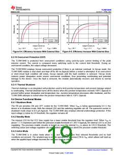
8.3.5 Switching Frequency (RT)
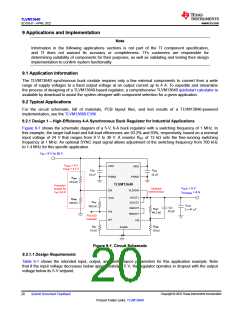
Connect a resistor, designated as RRT in Figure 8-1, between RT and AGND to set the swiching frequency within
the range of 200 kHz to 2.2 MHz. Use Equation 5 or refer to Figure 7-8 to calculate RRT for a desired frequency.
(5)
Refer to Table 8-1 or use the simplified expression in Equation 6 to find a switching frequency that sets an
inductor ripple current of 30% to 50% of the 4-A module current rating at nominal input voltage:
(6)
Copyright © 2022 Texas Instruments Incorporated
16
Submit Document Feedback
Product Folder Links: TLVM13640

 TI [ TEXAS INSTRUMENTS ]