TLVM13640
SLVSGJ7 – APRIL 2022
www.ti.com
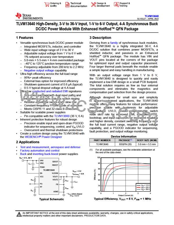
where
•
VIN(nom) and VOUT are the nominal input voltage (typically 12 V or 24 V) and output voltage of the application,
respectively.
Note that a resistor value outside of the recommended range can cause the module to shut down. This prevents
unintended operation if the RT pin is shorted to ground or left open.
8.3.6 Precision Enable and Input Voltage UVLO (EN)
The EN pin provides precision ON and OFF control for the TLVM13640. Once the EN pin voltage exceeds the
rising threshold and VIN is above its minimum turn-on threshold, the device starts operation. The simplest way
to enable the TLVM13640 is to connect EN directly to VIN. This allows the TLVM13640 to start up when VIN is
within its valid operating range. However, many applications benefit from the use of an enable divider network
as shown in Figure 8-1, which establishes a precision input undervoltage lockout (UVLO). This can be used for
sequencing, to prevent re-triggering the device when used with long input cables, or to reduce the occurrence of
deep discharge of a battery power source. An external logic signal can also be used to drive the enable input to
toggle the output on and off and for system sequencing or protection.
Calculate RENB using Equation 7:
(7)
where
•
•
•
A typical value for RENT is 100 kΩ.
VEN_RISE is enable rising threshold voltage of 1.263 V (typical).
VIN(on) is the desired start-up input voltage.
8.3.7 Power Good Monitor (PG)
The TLVM13640 provides a power-good status signal to indicate when the output voltage is within a regulation
window of 94% to 107%. The PG voltage goes low when the feedback (FB) voltage is outside of the specified
PGOOD thresholds (see Figure 7-7). This can occur during current limit and thermal shutdown, as well as when
disabled and during start-up.
PG is an open-drain output, requiring an external pullup resistor to a DC supply, such as VCC or VOUT. To
limit current supplied by VCC, the recommended range of pullup resistance is 20 kΩ to 100 kΩ. A 120-µs
deglitch filter prevents false flag operation for short excursions of the output voltage, such as during line and load
transients. When EN is pulled low, PG is forced low and remains remains valid as long as the input voltage is
above 1 V (typical). Use the PG signal for start-up sequencing of downstream regulators, as shown in Figure
8-2, or for fault protection and output monitoring.
VIN(on) = 13.9 V
VIN(off) = 10 V
VOUT2 = 3.3 V
VOUT1 = 5 V
RUV1
1 M
RFB3
PG 13
PG 13
RPG
RFB1
23.2 k
1 V
RFB4
100 k
14
EN
14
EN
40.2 k
RUV2
FB
10
FB
10
1 V
100 k
RFB2
10 k
10 k
Regulator #1
Regulator #2
Start-up based on
input voltage UVLO
Sequential start-up
based on PG
Figure 8-2. TLVM13640 Sequencing Implementation Using PG and EN
Copyright © 2022 Texas Instruments Incorporated
Submit Document Feedback
17
Product Folder Links: TLVM13640

 TI [ TEXAS INSTRUMENTS ]