TLVM13640
SLVSGJ7 – APRIL 2022
www.ti.com
9 Applications and Implementation
Note
Information in the following applications sections is not part of the TI component specification,
and TI does not warrant its accuracy or completeness. TI’s customers are responsible for
determining suitability of components for their purposes, as well as validating and testing their design
implementation to confirm system functionality.
9.1 Application Information
The TLVM13640 synchronous buck module requires only a few external components to convert from a wide
range of supply voltages to a fixed output voltage at an output current up to 4 A. To expedite and streamline
the process of designing of a TLVM13640-based regulator, a comprehensive TLVM13640 quickstart calculator is
available by download to assist the system designer with component selection for a given application.
9.2 Typical Applications
For the circuit schematic, bill of materials, PCB layout files, and test results of a TLVM13640-powered
implementation, see the TLVM13660 EVM.
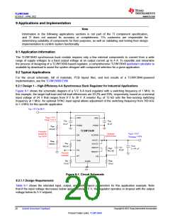
9.2.1 Design 1 – High-Efficiency 4-A Synchronous Buck Regulator for Industrial Applications
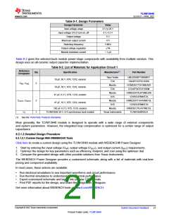
Figure 9-1 shows the schematic diagram of a 5-V, 6-A buck regulator with a switching frequency of 1 MHz. In
this example, the target half-load and full-load efficiencies are 93.2% and 93%, respectively, based on a nominal
input voltage of 24 V that ranges from 9 V to 36 V. A resistor RRT of 13 kΩ sets the free-running switching
frequency at 1 MHz. An optional SYNC input signal allows adjustment of the switching frequency from 700 kHz
to 1.4 MHz for this specific application.
VIN = 9 V to 36 V
VIN(on) = 6 V
VIN(off) = 4.3 V
VIN1
VIN2
CIN1
10
CIN2
10
F
F
PGND
PGND
RENT
374 k
TLVM13640
Precision
enable for
VIN UVLO
VOUT = 5 V
IOUT(max) = 4 A
Optional
external bias
EN
VLDOIN
VOUT1
VOUT2
VCC
RENB
RPG
100 k
100 k
COUT
CFF
22 pF
CBOOT
RBOOT
RFBT
2 ꢀ 47
F
PG
RT
40.2 k
PGOOD
indicator
FB
RRT
RFBB
10 k
AGND
13 k
Figure 9-1. Circuit Schematic
9.2.1.1 Design Requirements
Table 9-1 shows the intended input, output, and performance parameters for this application example. Note
that if the input voltage decreases below approximately 5.5 V, the regulator operates in dropout with the output
voltage below its 5-V setpoint.
Copyright © 2022 Texas Instruments Incorporated
20
Submit Document Feedback
Product Folder Links: TLVM13640

 TI [ TEXAS INSTRUMENTS ]