TLVM13640
SLVSGJ7 – APRIL 2022
www.ti.com
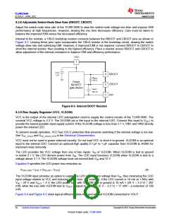
100
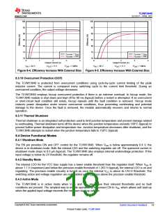
100
95
90
85
80
75
70
95
90
85
80
75
VVLDOIN = VOUT
VVLDOIN = GND
VVLDOIN = VOUT
VVLDOIN = GND
70
0
1
2
3
4
0
1
2
3
4
Output Current (A)
Output Current (A)
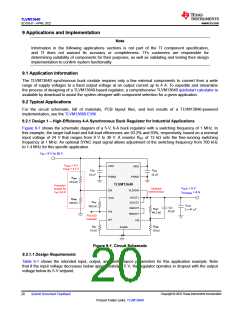
VIN = 24 V
VOUT = 5 V
FSW = 1 MHz
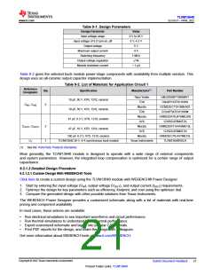
VIN = 36 V
VOUT = 5 V
FSW = 1 MHz
Figure 8-4. Efficiency Increase With External Bias Figure 8-5. Efficiency Increase With External Bias
8.3.10 Overcurrent Protection (OCP)
The TLVM13640 is protected from overcurrent conditions using cycle-by-cycle current limiting of the peak
inductor current. The current is compared every switching cycle to the current limit threshold. During an
overcurrent condition, the output voltage decreases.
The TLVM13640 employs hiccup overcurrent protection if there is an extreme overload. In hiccup mode, the
TLVM13640 module is shut down and kept off for 80 ms (typical) before a restart is attempted. If an overcurrent
or short-circuit fault condition still exists, hiccup repeats until the fault condition is removed. Hiccup mode
reduces power dissipation under severe overcurrent conditions, thus preventing overheating and potential
damage to the device. Once the fault is removed, the module automatically recovers and returns to normal
operation.
8.3.11 Thermal Shutdown
Thermal shutdown is an integrated self-protection used to limit junction temperature and prevent damage related
to overheating. Thermal shutdown turns off the device when the junction temperature exceeds 168°C (typical) to
prevent further power dissipation and temperature rise. Junction temperature decreases after shutdown, and the
TLVM13640 attempts to restart when the junction temperature falls to 158°C (typical).
8.4 Device Functional Modes
8.4.1 Shutdown Mode
The EN pin provides ON and OFF control for the TLVM13640. When VEN is below approximately 0.4 V, the
device is in shutdown mode. Both the internal LDO and the switching regulator are off. The quiescent current in
shutdown mode drops to 0.6 µA (typical). The TLVM13640 also employs internal undervoltage protection. If the
input voltage is below its UV threshold, the regulator remains off.
8.4.2 Standby Mode
The internal LDO for the VCC bias supply has a lower enable threshold than the regulator itself. When VEN is
above 1.1 V (maximum) and below the precision enable threshold of 1.263 V (typical), the internal LDO is on and
regulating. The precision enable circuitry is turned on once the internal VCC is above its UVLO threshold. The
switching action and voltage regulation are not enabled until VEN rises above the precision enable threshold.
8.4.3 Active Mode
The TLVM13640 is in active mode when VVCC and VEN are above their relevant thresholds and no fault
conditions are present. The simplest way to enable operation is to connect EN to VIN, which allows self start-up
when the applied input voltage exceeds the minimum start-up voltage.
Copyright © 2022 Texas Instruments Incorporated
Submit Document Feedback
19
Product Folder Links: TLVM13640

 TI [ TEXAS INSTRUMENTS ]