PGA400-Q1
www.ti.com
SLDS186 –MARCH 2012
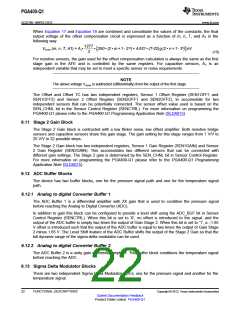
6.13.1 Sigma Delta Modulator for AD Converter 1
The Sigma Delta Modulator 1 block is a 1-bit 1MHz sigma-delta modulator for the pressure sensor signal.
To further condition the signal this stage is followed by two stages of digital decimation filters.
6.13.2 Sigma Delta Modulator for AD Converter 2
The Sigma Delta Modulator 2 block is a 1-bit 128kHz sigma-delta modulator for the temperature signal.
The input signal to the sigma-delta modulator can come from either the internal or external temperature.
The output of this ADC is followed by a single decimation filter.
6.14 Decimation Filter Blocks
The device contains three Signal Decimation FIlters. Two back to back decimation filters for the pressure
sensor signal path and one decimation filter for the termperature path.
6.14.1 ADC1 Decimation Filter Blocks
The sensor signal path contains two decimation filters in series with each other. The first decimation filter
has a fixed decimation ratio and a second decimation filter that has a variable decimation ratio.
The 1st Stage Decimator Filter has a fixed decimation ratio of 32. Based on the 1MHz sampling frequency
of the sigma-delta modulator, the output rate of the 1st stage decimator is fixed at 32 µs per sample.
The 2nd Stage Decimator has a variable decimation ratio. This filter further decimates the output of the
first stage decimator. The decimation ratios of the second stage can be configured for a decimation ratio
of 2, 4, or 8 using the OSR[1..0] bits in the Decimator and Low Power Control Register (DECCTRL). For
more information on programming the PGA400-Q1 please refer to the PGA400-Q1 Programming
Application Note (SLDA015).
The output of the second decimation filter in the sensors signal path is a 16 bit signed value. Some
example second stage decimation output codes for given differential voltages at the input of the sigma
delta modulator are shown in Table 6-3:
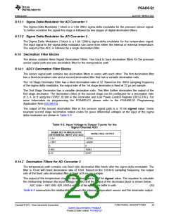
Table 6-3. Input Voltage to Output Counts for the
Signal Channel ADC
SIGMA DELTA MODULATOR
NOISE-FREE OUTPUT
DIFFERENTIAL INPUT VOLTAGE
–3.3V
–1.65V
0
–32768
–16384
0
1.65V
3.3V
16383
32767
6.14.2 Decimation Filters for AD Converter 2
The temperature path contains one fixed ratio decimation filter block after the sigma delta modulator. The
filter is 10-bit with fixed decimation ratio of 1024. Based on the 128-kHz sampling frequency, the output
rate of the fixed ratio decimation filter is fixed at 8 ms per sample.
The output of the temperature channel decimation filter is a 10 bit signed value. The equation to calculate
the relationship between the input voltage at VIN3 and the output of the decimator block is shown below.
ADC Code = 760* VIN3 -820, VIN3 is voltage at the input of the buffer in volts.
(20)
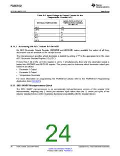
Table 6-4 summarizes the relationship between the internal temperature sensor and the decimator output.
Copyright © 2012, Texas Instruments Incorporated
FUNCTIONAL DESCRIPTIONS
23
Submit Documentation Feedback
Product Folder Link(s): PGA400-Q1

 TI [ TEXAS INSTRUMENTS ]