PGA400-Q1
www.ti.com
SLDS186 –MARCH 2012
I
I
I
(a)
X
A
B
I
C
I
/2
C
-I /2
C
-I
C
I
2
(b)
I
1
I
/2
C
-I /2
C
(c)
I
P
I
/2
I
C
N
-I /2
C
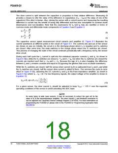
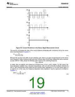
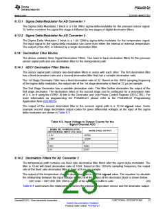
Figure 6-5. Current Waveforms in the Sensor Signal Measurement Circuit
This process of changing the state of the circuit continues periodically with a frequency set by the sensor
drive circuit described in Equation 11.
IC
f =
2•VH •(CA+ CB)
(11)
BEcause the op-amp must settle at each switching cycle, there is an upper bound imposed on the sensor
drive frequency. Using a minimum half-cycle time of seven times the op-amp settling time and a minimum
op-amp GBW of 7 MHz, shows the following upper bound on the switching frequency:
ƒMAX ≤ 800 kHz
In reality, there are glitches and residual up-converted noise in the IP and IN signals. For this reason, the
trans-impedance amplifier has a low-pass characteristic, with one pole set by the feedback elements Rf
and Cf, and a second pole at the output set by R and the same capacitance Cf. For most sensor types, R
is equal to Rf. In this case, the frequency dependent trans-impedance may be expressed as shown in
Equation 12.
Rf
1+ s• Rf • Cf)2
Z(s)=
W
(12)
Copyright © 2012, Texas Instruments Incorporated
FUNCTIONAL DESCRIPTIONS
19
Submit Documentation Feedback
Product Folder Link(s): PGA400-Q1

 TI [ TEXAS INSTRUMENTS ]