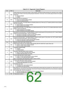
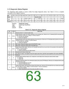
5.15 Diagnostic Status Register
The diagnostic status register is used to reflect the bridge diagnostic status. See Table 5–13 for a complete
description of the register contents.
Bit
15
14
13
12
11
10
9
8
7
6
5
4
3
2
1
0
Name
Diagnostic status
R/C/
U
R/C/
U
R/C/
R/C/
U
Type
R
0
R
0
R
0
R
0
R
0
R
U
R
0
R
0
R
0
R
0
R
X
R
X
Default
X
X
0
0
X
Register:
Type:
Diagnostic status
Read-only, Read/Write
Offset:
Default:
5Eh
0X0Xh
Table 5–13. Diagnostic Status Register
BIT
TYPE
FUNCTION
15–12
R
Reserved. Bits 15–12 return 0s when read.
Bridge detected a parity error while mastering on the secondary bus. When set, bit 11 indicates that the secondary bus
master detected a parity error. Writing a 1 to this bit clears it.
0 = No parity error detected
11
10
R/C/U
1 = Parity error detected
Bridge detected a parity error while mastering on the primary bus. When set, bit 10 indicates that the primary bus master
detected a parity error. Writing a 1 to this bit clears it.
0 = No parity error detected
R/C/U
1 = Parity error detected
9
8
R
R
MS1 status. Returns the logical value of the MS1/BPCC input.
MS0 status. Returns the logical value of the MS0 input.
Arbiter timeout SERR status. When set, bit 0 indicates that SERR has occurred due to the expiration of the arbiter timer.
Writing a 1 to this bit clears it.
0 = No SERR (default)
7
R/C/U
1 = SERR occurred due to an arbiter timeout
6
5
R
R
R
Reserved. Bit 6 returns 0 when read.
HS_SWITCH status. This registers returns the logical value of the S_MFUNC input regardless of the value of MS0/MS1.
Reserved
4–3
External arbiter enable pin status. Bit 2 contains the current state of the external pin external arbiter enable.
2
1
R
0 = Signal low
1 = Signal high
Serial EEPROM block status. Bit 1 indicates the status of the serial EEPROM block. When set, bit 1 indicates that the serial
EEPROM block is busy.
R
0 = Serial EEPROM block not busy
1 = Serial EEPROM block busy
Arbiter timeout status. Bit 0 indicates the status of the arbiter timer. When set, bit 0 indicates that a bus master did not begin
the cycle within 16 clocks. Writing a 1 to this bit clears it. This bit is encoded as:
0 = No timeout (default).
0
R/C/U
1 = Master requesting the bus did not start cycle within 16 clocks.
5–13

 TI [ TEXAS INSTRUMENTS ]