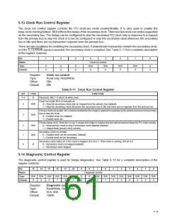
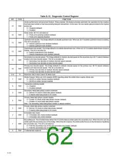
Table 5–12. Diagnostic Control Register
BIT
TYPE
FUNCTION
Arbiter performance enhancement feature. When enabled, this feature provides automatic tier operation for bus masters
that have been retried or that have pending delayed transactions. In this case, the bus master gets promoted to the highest
priority tier.
15
R/W
0 = Disabled (default)
1 = Enabled
Parity mode. Bit 14 is encoded as:
0 = Parity error passing enabled (default)
1 = Parity error passing disabled
14
13
R/W
R/W
Upstream lock enable. The bridge default is to disable upstream lock. When set, bit 13 enables upstream resource locking.
This bit is encoded as:
0 = Selects upstream lock disabled (default)
1 = Selects upstream lock enabled
Downstream lock enable. The bridge default is to enable downstream lock. When set, bit 12 enables downstream resource
locking. This bit is encoded as:
12
11
10
R/W
R/W
R/W
0 = Selects downstream lock disabled
1 = Selects downstream lock enabled (default)
Secondary-bus decode speed. The bridge defaults to medium decode speed on the secondary bus. Bit 11 selects between
medium and slow decode speed. This bit is encoded as:
0 = Secondary bus decodes at medium decode speed (default)
1 = Secondary bus decodes at slow decode speed
Primary-bus decode speed. The bridge defaults to medium decode speed on the primary bus. Bit 10 selects between
medium and slow decode speed. This bit is encoded as:
0 = Primary bus decodes at medium decode speed (default)
1 = Primary bus decodes at slow decode speed
9–8
7
R
Reserved. Bits 9 and 8 return 0s when read.
Arbiter timeout. When set, bit 0 enables SERR reporting when the arbiter timer expires (times out).
0 = SERR on arbiter timeout disabled (default)
R/W
1 = SERR on arbiter timeout enabled
Transaction ordering enable
0 = Disabled
6
5
R/W
R/W
1 = Enabled (default)
Secondary initial data phase counter extension
0 = Normal 16 clock to initial data phase (default)
1 = Extends initial data phase to 64 clocks
Primary initial data phase counter disable
0 = Enable 16 clocks initial data phase counter (default)
1 = Disable 16 clock initial data phase counter
4
R/W
Note: The secondary initial data phase counter is always enabled.
Primary initial data phase counter extension
0 = Normal 16 clocks to initial data phase (default)
1 = Extends initial data phase to 64 clocks
3
2
R/W
R/W
Immediate retry mode
0 = Immediate retry mode enabled (default)
1 = Immediate retry mode disabled
Bus parking bit. This bit determines where the PCI2250 internal arbiter parks the secondary bus. When this bit is set, the
arbiterparks the secondary bus on the bridge. When this bit is cleared, the arbiter parks the bus on the last device mastering
the secondary bus. This bit is encoded as:
1
0
R/W
R/W
0 = Park the secondary bus on the last secondary bus master (default)
1 = Park the secondary bus on the bridge
TI internal test mode bit.
5–12

 TI [ TEXAS INSTRUMENTS ]