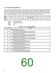
5.12 Port Decode Map Register
The port decode map register is used to select whether the serial- and parallel-port address ranges positively
decoded from the primary bridge interface to the secondary interface are included or excluded from the primary
interface. For example, if bit 0 is set, then addresses in the range of 3F8h–3FFh are positively decoded on the primary
bus. If bit 0 is cleared and an I/O window is enabled that covers the range from 3F8h–3FFh, then these addresses
are not claimed by the bridge. See Table 5–10 for a complete description of the register contents.
Bit
7
6
5
4
3
2
1
0
Name
Type
Default
Port decode map
R/W R/W
R
0
R/W
0
R/W
0
R/W
0
R/W
0
R/W
0
0
0
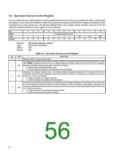
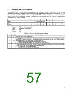
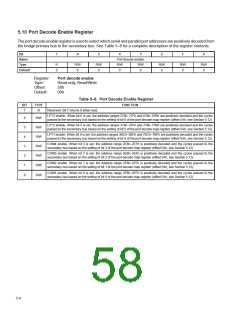
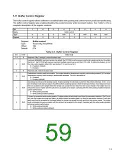
Register:
Type:
Port decode map
Read-only, Read/Write
Offset:
Default:
5Ah
00h
Table 5–10. Port Decode Map Register
BIT
TYPE
FUNCTION
7
R
Reserved. Bit 7 returns 0 when read.
LPT3 include/exclude. Bit 6 is encoded as:
6
5
4
3
2
1
0
R/W
0 = 278h–27Fh and 678h–67Bh excluded from the primary bus (default)
1 = 278h–27Fh and 678h–67Bh positively decoded on the primary bus
LPT2 include/exclude. Bit 5 is encoded as:
R/W
R/W
R/W
R/W
R/W
R/W
0 = 378h–37Fh and 778h–77Bh excluded from the primary bus (default)
1 = 378h–37Fh and 778h–77Bh positively decoded on the primary bus
LPT1 include/exclude. Bit 4 is encoded as:
0 = 3BCh–3BFh and 7BCh–7BFh excluded from the primary bus (default)
1 = 3BCh–3BFh and 7BCh–7BFh positively decoded on the primary bus
COM4 include/exclude. Bit 3 is encoded as:
0 = 2E8h–2EFh excluded from the primary bus (default)
1 = 2E8h–2EFh positively decoded on the primary bus
COM3 include/exclude. Bit 2 is encoded as:
0 = 3E8h–3EFh excluded from the primary bus (default)
1 = 3E8h–3EFh positively decoded on the primary bus
COM2 include/exclude. Bit 1 is encoded as:
0 = 2F8h–2FFh excluded from the primary bus (default)
1 = 2F8h–2FFh positively decoded on the primary bus
COM1 include/exclude. Bit 0 is encoded as:
0 = 3F8h–3FFh excluded from the primary bus (default)
1 = 3F8h–3FFh positively decoded on the primary bus
5–10

 TI [ TEXAS INSTRUMENTS ]