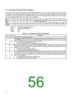
5.8 Secondary Decode Control Register
The secondary decode control register is used to enable/disable the secondary-bus negative decoding. Only through
this register can an extension window be defined for positive decoding or excluded from negative decoding from the
secondary bus to the primary bus. The window interface bits in the window control registers must be set for the
extension window definitions in this register to have meaning.
Bit
7
6
5
4
3
2
1
0
Name
Type
Default
Secondary decode control
R
0
R
0
R
0
R
0
R
0
R/W
1
R/W
1
R/W
0
Register:
Type:
Secondary decode control
Read-only, Read/Write
Offset:
Default:
56h
06h
Table 5–6. Secondary Decode Control Register
BIT
TYPE
FUNCTION
7–3
R
Reserved. Bits 7–3 return 0s when read.
Secondary-bussubtractivedecodespeed. Thebridgedefaultstosubtractivedecodingafterslowdecodespeed(fourclocks
after FRAME is asserted). Bit 0 must be set to enable subtractive decoding. When bit 0 and this bit are set, subtractive
decoding is enabled at slow decode speed. This bit is encoded as:
2
1
R/W
0 = Selects normal subtractive decode speed.
1 = Selects subtractive decode in the slow decode time slot (default).
Secondary bus negative decode enable. The bridge defaults to negative decoding on the secondary PCI bus. All
transactions that do not fall into windows positively decoded from the primary to the secondary are passed through to the
primary bus. This bit is encoded as:
R/W
R/W
0 = Disable secondary-bus negative decoding.
1 = Enable secondary-bus negative decoding (default).
Secondary-bussubtractive decode enable. The bridge defaults to negative decoding on the secondary PCI bus. When bit 0
is set, the bridge uses subtractive decoding on the secondary bus. When the bridge is using negative decoding on the
secondary, all transactions not claimed by a slow device on the secondary bus are passed through the bridge to the primary
bus. This bit is encoded as:
0
0 = Disable secondary bus subtractive decoding (default).
1 = Enable secondary bus subtractive decoding.
5–6

 TI [ TEXAS INSTRUMENTS ]