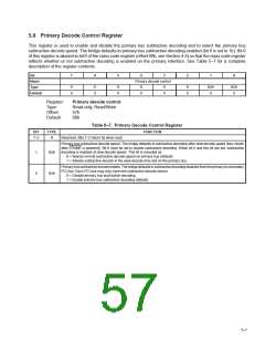
5.9 Primary Decode Control Register
This register is used to enable and disable the primary bus subtractive decoding and to select the primary bus
subtractive decode speed. The bridge defaults to primary bus subtractive decoding enabled (bit 0 is set to 1b). Bit 0
of this register is aliased to bit 0 of the class code register (offset 09h, see Section 4.6) so that the class code register
reflects whether or not subtractive decoding is enabled on the primary interface. See Table 5–7 for a complete
description of the register contents.
Bit
7
6
5
4
3
2
1
0
Name
Type
Default
Primary decode control
R
0
R
0
R
0
R
0
R
0
R
0
R/W
0
R/W
0
Register:
Type:
Primary decode control
Read-only, Read/Write
Offset:
Default:
57h
00h
Table 5–7. Primary Decode Control Register
BIT
TYPE
FUNCTION
7–2
R
Reserved. Bits 7–2 return 0s when read.
Primary-bus subtractive decode speed. The bridge defaults to subtractive decoding after slow decode speed (four clocks
after FRAME is asserted). Bit 0 must be set to enable subtractive decoding. When bit 0 and this bit are set, subtractive
decoding is enabled at slow decode speed. This bit is encoded as:
1
0
R/W
0 = Selects normal subtractive decode speed on primary bus (default)
1 = Selects subtractive decode in the slow decode time slot on the primary bus
Primary-bussubtractivedecodeenable. Thebridgedefaultstosubtractivedecodingdisabledfromtheprimarytosecondary
PCI bus. Each PCI bus may only have one subtractive decode device.
0 = Disable primary bus subtractive decoding
R/W
1 = Enable primary bus subtractive decoding (default)
5–7

 TI [ TEXAS INSTRUMENTS ]