ADS1299
www.ti.com
SBAS499A –JULY 2012–REVISED AUGUST 2012
PGA SETTINGS AND INPUT RANGE
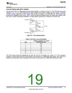
The low-noise PGA is a differential input and output amplifier, as shown in Figure 23. The PGA has seven gain
settings (1, 2, 4, 6, 8, 12, and 24) that can be set by writing to the CHnSET register (see the CHnSET: Individual
Channel Settings subsection of the Register Map section for details). The ADS1299 has CMOS inputs and
therefore has negligible current noise. Table 5 shows the typical bandwidth values for various gain settings. Note
that Table 5 shows small-signal bandwidth. For large signals, performance is limited by PGA slew rate.
From MuxP
Low-Noise
PgaP
R2
18.15 kW
R1
3.3 kW
(for Gain = 12)
To ADC
R2
18.15 kW
Low-Noise
PgaN
From MuxN
Figure 23. PGA Implementation
Table 5. PGA Gain versus Bandwidth
NOMINAL BANDWIDTH AT ROOM
GAIN
TEMPERATURE (kHz)
1
2
662
332
165
110
83
4
6
8
12
24
55
27
The PGA resistor string that implements the gain has 39.6 kΩ of resistance for a gain of 12. This resistance
provides a current path across the PGA outputs in the presence of a differential input signal. This current is in
addition to the quiescent current specified for the device in the presence of a differential signal at the input.
Copyright © 2012, Texas Instruments Incorporated
Submit Documentation Feedback
19
Product Folder Link(s): ADS1299

 TI [ TEXAS INSTRUMENTS ]