ADS1299
www.ti.com
SBAS499A –JULY 2012–REVISED AUGUST 2012
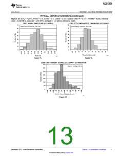
Device Noise Measurements
Setting CHnSET[2:0] = 001 sets the common-mode voltage of [(VREFP + VREFN) / 2] to both channel inputs.
This setting can be used to test inherent device noise in the user system.
Test Signals (TestP and TestN)
Setting CHnSET[2:0] = 101 provides internally-generated test signals for use in sub-system verification at power-
up. This functionality allows the device internal signal chain to be tested out.
Test signals are controlled through register settings (see the CONFIG2: Configuration Register 2 subsection in
the Register Map section for details). TEST_AMP controls the signal amplitude and TEST_FREQ controls
switching at the required frequency.
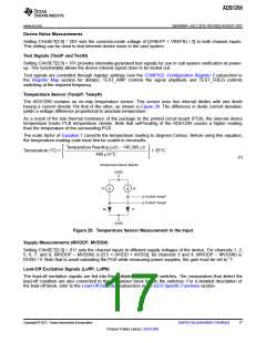
Temperature Sensor (TempP, TempN)
The ADS1299 contains an on-chip temperature sensor. This sensor uses two internal diodes with one diode
having a current density 16x that of the other, as shown in Figure 20. The difference in diode current densities
yields a voltage difference proportional to absolute temperature.
As a result of the low thermal resistance of the package to the printed circuit board (PCB), the internal device
temperature tracks PCB temperature closely. Note that self-heating of the ADS1299 causes a higher reading
than the temperature of the surrounding PCB.
The scale factor of Equation 1 converts the temperature reading to degrees Celsius. Before using this equation,
the temperature reading code must first be scaled to microvolts.
Temperature Reading (mV) - 145,300 mV
Temperature (°C) =
+ 25°C
490 mV/°C
(1)
Temperature Sensor Monitor
AVDD
1x
2x
To MUX TempP
To MUX TempN
8x
1x
AVSS
Figure 20. Temperature Sensor Measurement in the Input
Supply Measurements (MVDDP, MVDDN)
Setting CHnSET[2:0] = 011 sets the channel inputs to different supply voltages of the device. For channels 1, 2,
5, 6, 7, and 8, (MVDDP – MVDDN) is [0.5 × (AVDD + AVSS)]; for channels 3 and 4, (MVDDP – MVDDN) is
DVDD / 4. Note that to avoid saturating the PGA while measuring power supplies, the gain must be set to '1'.
Lead-Off Excitation Signals (LoffP, LoffN)
The lead-off excitation signals are fed into the multiplexer before the switches. The comparators that detect the
lead-off condition are also connected to the multiplexer block before the switches. For a detailed description of
the lead-off block, refer to the Lead-Off Detection subsection in the EEG-Specific Functions section.
Copyright © 2012, Texas Instruments Incorporated
Submit Documentation Feedback
17
Product Folder Link(s): ADS1299

 TI [ TEXAS INSTRUMENTS ]