ADS1299
SBAS499A –JULY 2012–REVISED AUGUST 2012
www.ti.com
Auxiliary Single-Ended Input
The BIASIN pin is primarily used for routing the bias signal to any electrodes in case the bias electrode falls off.
However, the BIASIN pin can be used as a multiple single-ended input channel. The signal at the BIASIN pin can
be measured with respect to the voltage at the BIASREF pin using any of the eight channels. This measurement
is done by setting the channel multiplexer setting to '010' and the BIAS_MEAS bit of the CONFIG3 register to '1'.
ANALOG INPUT
The ADS1299 analog input is fully differential. Assuming PGA = 1, the input (INP – INN) can span between
–VREF to +VREF. Refer to Table 7 for an explanation of the correlation between the analog input and digital codes.
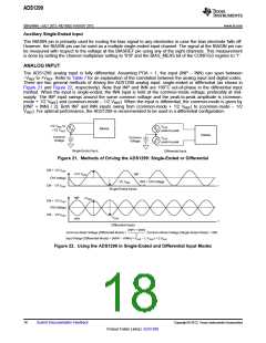
There are two general methods of driving the ADS1299 analog input: single-ended or differential (as shown in
Figure 21 and Figure 22, respectively). Note that INP and INN are 180°C out-of-phase in the differential input
method. When the input is single-ended, the INN input is held at the common-mode voltage, preferably at mid-
supply. The INP input swings around the same common voltage and the peak-to-peak amplitude is (common-
mode + 1/2 VREF) and (common-mode – 1/2 VREF). When the input is differential, the common-mode is given by
[(INP + INN) / 2]. Both INP and INN inputs swing from (common-mode + 1/2 VREF) to (common-mode – 1/2
VREF). For optimal performance, the ADS1299 is recommended to be used in a differential configuration.
-1/2 VREF to
VREF
Device
+1/2 VREF
peak-to-peak
Device
Common
Voltage
Common
Voltage
VREF
peak-to-peak
Single-Ended Input
Differential Input
Figure 21. Methods of Driving the ADS1299: Single-Ended or Differential
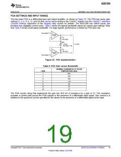
CM + 1/2 VREF
+1/2 VREF
INP
CM Voltage
-1/2 VREF
INN = CM Voltage
CM - 1/2 VREF
t
Single-Ended Inputs
INP
INN
+VREF
CM + 1/2 VREF
CM Voltage
CM - 1/2 VREF
-VREF
t
Differential Inputs
(INP) + (INN)
, Common-Mode Voltage (Single-Ended Mode) = INN.
Common-Mode Voltage (Differential Mode) =
2
Input Range (Differential Mode) = (AINP - AINN) = VREF - (-VREF) = 2 VREF
.
Figure 22. Using the ADS1299 in Single-Ended and Differential Input Modes
18
Submit Documentation Feedback
Copyright © 2012, Texas Instruments Incorporated
Product Folder Link(s): ADS1299

 TI [ TEXAS INSTRUMENTS ]