ADS1299
SBAS499A –JULY 2012–REVISED AUGUST 2012
www.ti.com
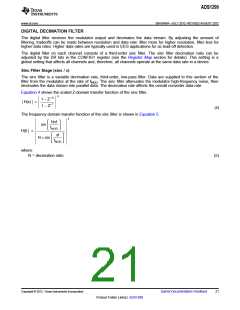
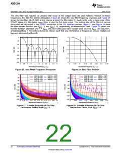
The sinc filter has notches (or zeroes) that occur at the output data rate and multiples thereof. At these
frequencies, the filter has infinite attenuation. Figure 25 shows the sinc filter frequency response and Figure 26
shows the sinc filter roll-off. With a step change at input, the filter takes 3 × tDR to settle. After a rising edge of the
START signal, the filter takes tSETTLE time to give the first data output. The settling time of the filters at various
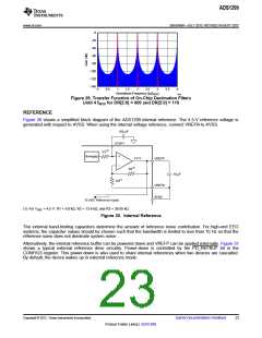
data rates are discussed in the START subsection of the SPI Interface section. Figure 27 and Figure 28 show
the filter transfer function until fMOD / 2 and fMOD / 16, respectively, at different data rates. Figure 29 shows the
transfer function extended until 4 × fMOD. The ADS1299 pass band repeats itself at every fMOD. The input R-C
antialiasing filters in the system should be chosen such that any interference in frequencies around multiples of
fMOD are attenuated sufficiently.
0
-0.5
-1
0
-20
-40
-60
-1.5
-2
-80
-100
-120
-140
-2.5
-3
0
0.05
0.1
0.15
0.2
0.25
0.3
0.35
0
0.5
1
1.5
2
2.5
3
3.5
4
4.5
5
Normalized Frequency (fIN / fDR
)
Normalized Frequency (fIN / fDR
)
Figure 25. Sinc Filter Frequency Response
Figure 26. Sinc Filter Roll-Off
0
0
DR[2:0] = 000
DR[2:0] = 001
DR[2:0] = 010
DR[2:0] = 011
DR[2:0] = 100
DR[2:0] = 101
DR[2:0] = 110
DR[2:0] = 000
DR[2:0] = 001
DR[2:0] = 010
DR[2:0] = 011
DR[2:0] = 100
DR[2:0] = 101
DR[2:0] = 110
−20
−40
−20
−40
−60
−60
−80
−80
−100
−120
−140
−160
−100
−120
−140
0
0.05 0.1 0.15 0.2 0.25 0.3 0.35 0.4 0.45 0.5
Normalized Frequency (fIN/fMOD
0
0.01
0.02
0.03
0.04
0.05
0.06
0.07
)
Normalized Frequency (fIN/fMOD
)
G027
G028
Figure 27. Transfer Function of On-Chip
Decimation Filters Until fMOD / 2
Figure 28. Transfer Function of On-Chip
Decimation Filters Until fMOD / 16
22
Submit Documentation Feedback
Copyright © 2012, Texas Instruments Incorporated
Product Folder Link(s): ADS1299

 TI [ TEXAS INSTRUMENTS ]