ADS1299
SBAS499A –JULY 2012–REVISED AUGUST 2012
www.ti.com
OVERVIEW
The ADS1299 is a low-noise, low-power, multichannel, simultaneously-sampling, 24-bit, delta-sigma (ΔΣ) analog-
to-digital converter (ADC) with an integrated programmable gain amplifier (PGA). This device integrates various
EEG-specific functions that makes it well-suited for scalable electroencephalography (EEG) applications. The
device can also be used in high-performance, multichannel, data acquisition systems by powering down the
EEG-specific circuitry.
The ADS1299 has a highly-programmable multiplexer that allows for temperature, supply, input short, and bias
measurements. Additionally, the multiplexer allows any input electrodes to be programmed as the patient
reference drive. The PGA gain can be chosen from one of seven settings (1, 2, 4, 6, 8, 12, and 24). The ADCs in
the device offer data rates from 250 SPS to 16 kSPS. Communication to the device is accomplished using an
SPI-compatible interface. The device provides four general-purpose input/output (GPIO) pins for general use.
Multiple devices can be synchronized using the START pin.
The internal reference can be programmed to 4.5 V. The internal oscillator generates a 2.048-MHz clock. The
versatile patient bias drive block allows the average of any electrode combination to be chosen in order to
generate the patient drive signal. Lead-off detection can be accomplished by using a current source or sink. A
one-time, in-band, lead-off option and a continuous, out-of-band, internal lead-off option are available. Refer to
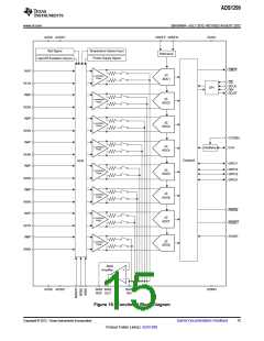
Figure 18 for a block diagram.
14
Submit Documentation Feedback
Copyright © 2012, Texas Instruments Incorporated
Product Folder Link(s): ADS1299

 TI [ TEXAS INSTRUMENTS ]