ADS1115-Q1
www.ti.com
SBAS563 –DECEMBER 2011
When the master has finished communicating with a
slave, it may issue a STOP condition. When a STOP
condition is issued, the bus becomes idle again. The
master may also issue another START condition.
When a START condition is issued while the bus is
active, it is called a repeated START condition.
For more information on high-speed mode, consult
the I2C specification.
SLAVE MODE OPERATIONS
The ADS1115-Q1 can act as either slave receivers or
slave transmitters. As
a
slave device, the
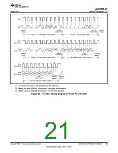
See the Timing Requirements section for a timing
ADS1115-Q1 cannot drive the SCL line.
diagram showing the ADS1115-Q1 I2C transaction.
Receive Mode:
I2C ADDRESS SELECTION
In slave receive mode the first byte transmitted from
the master to the slave is the address with the R/W
bit low. This byte allows the slave to be written to.
The next byte transmitted by the master is the
register pointer byte. The ADS1115-Q1 then
acknowledge receipt of the register pointer byte. The
next two bytes are written to the address given by the
register pointer. The ADS1115-Q1 acknowledge each
byte sent. Register bytes are sent with the most
significant byte first, followed by the least significant
byte.
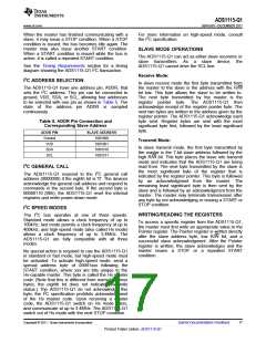
The ADS1115-Q1 have one address pin, ADDR, that
sets the I2C address. This pin can be connected to
ground, VDD, SDA, or SCL, allowing four addresses
to be selected with one pin as shown in Table 5. The
state of the address pin ADDR is sampled
continuously.
Table 5. ADDR Pin Connection and
Corresponding Slave Address
ADDR PIN
Ground
VDD
SLAVE ADDRESS
1001000
Transmit Mode:
1001001
In slave transmit mode, the first byte transmitted by
the master is the 7-bit slave address followed by the
high R/W bit. This byte places the slave into transmit
mode and indicates that the ADS1115-Q1 are being
read from. The next byte transmitted by the slave is
the most significant byte of the register that is
indicated by the register pointer. This byte is followed
by an acknowledgment from the master. The
remaining least significant byte is then sent by the
slave and is followed by an acknowledgment from the
master. The master may terminate transmission after
any byte by not acknowledging or issuing a START or
STOP condition.
SDA
1001010
SCL
1001011
I2C GENERAL CALL
The ADS1115-Q1 respond to the I2C general call
address (0000000) if the eighth bit is '0'. The devices
acknowledge the general call address and respond to
commands in the second byte. If the second byte is
00000110 (06h), the ADS1115-Q1 reset the internal
registers and enter power-down mode.
I2C SPEED MODES
The I2C bus operates at one of three speeds.
Standard mode allows a clock frequency of up to
100kHz; fast mode permits a clock frequency of up to
400kHz; and high-speed mode (also called Hs mode)
allows a clock frequency of up to 3.4MHz. The
ADS1115-Q1 are fully compatible with all three
modes.
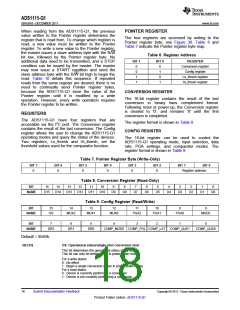
WRITING/READING THE REGISTERS
To access a specific register from the ADS1115-Q1,
the master must first write an appropriate value to the
Pointer register. The Pointer register is written directly
after the slave address byte, low R/W bit, and a
successful slave acknowledgment. After the Pointer
register is written, the slave acknowledges and the
master issues
condition.
a STOP or a repeated START
No special action is required to use the ADS1115-Q1
in standard or fast mode, but high-speed mode must
be activated. To activate high-speed mode, send a
special address byte of 00001xxx following the
START condition, where xxx are bits unique to the
Hs-capable master. This byte is called the Hs master
code. (Note that this is different from normal address
bytes; the eighth bit does not indicate read/write
status.) The ADS1115-Q1 do not acknowledge this
byte; the I2C specification prohibits acknowledgment
of the Hs master code. Upon receiving a master
code, the ADS1115-Q1 switch on Hs mode filters,
and communicate at up to 3.4MHz. The ADS1115-Q1
switch out of Hs mode with the next STOP condition.
Copyright © 2011, Texas Instruments Incorporated
Submit Documentation Feedback
17
Product Folder Link(s) :ADS1115-Q1

 TI [ TEXAS INSTRUMENTS ]