ADS1115-Q1
www.ti.com
SBAS563 –DECEMBER 2011
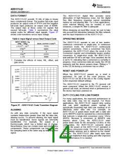
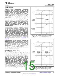
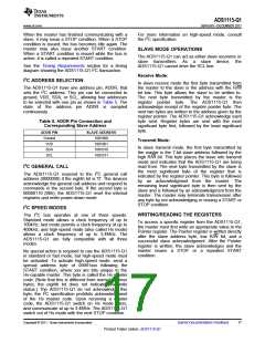
COMPARATOR
The ADS1115-Q1 is equipped with a customizable
comparator that can issue an alert on the
ALERT/RDY pin. This feature can significantly reduce
external circuitry for many applications. The
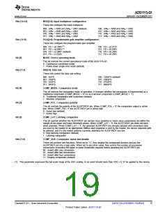
TH_H
TH_L
Input Signal
comparator can be implemented as either
a
traditional comparator or a window comparator via the
COMP_MODE bit in the Config register. When
Time
implemented as
a
traditional comparator, the
ALERT/RDY pin asserts (active low by default) when
conversion data exceed the limit set in the high
threshold register. The comparator then deasserts
when the input signal falls below the low threshold
register value. In window comparator mode, the
ALERT/RDY pin asserts if conversion data exceed
the high threshold register or fall below the low
threshold register.
Successful
SMBus Alert
Response
Latching
Comparator
Output
Time
In either window or traditional comparator mode, the
comparator can be configured to latch once asserted
by the COMP_LAT bit in the Config register. This
setting causes the assertion to remain even if the
input signal is not beyond the bounds of the threshold
registers. This latched assertion can be cleared by
issuing an SMBus alert response or by reading the
Conversion register. The COMP_POL bit in the
Config register configures the ALERT/RDY pin as
active high or active low. Operational diagrams for
the comparator modes are shown in Figure 28 and
Figure 29.
Non-Latching
Comparator
Output
Time
Figure 28. Alert Pin Timing Diagram When
Configured as a Traditional Comparator
The comparator can be configured to activate the
ALERT/RDY pin after a set number of successive
readings exceed the threshold. The comparator can
be configured to wait for one, two, or four readings
beyond the threshold before activating the
ALERT/RDY pin by changing the COMP_QUE bits in
the Config register. The COMP_QUE bits can also
disable the comparator function.
TH_H
Input Signal
TH_L
Time
CONVERSION READY PIN
Latching
Comparator
Output
Successful
SMBus Alert
Response
Successful
SMBus Alert
Response
The ALERT/RDY pin can also be configured as a
conversion ready pin. This mode of operation can be
realized if the MSB of the high threshold register is
set to '1' and the MSB of the low threshold register is
set to '0'. The COMP_POL bit continues to function
and the COMP_QUE bits can disable the pin;
however, the COMP_MODE and COMP_LAT bits no
longer control any function. When configured as a
conversion ready pin, ALERT/RDY continues to
Time
Non-Latching
Comparator
Output
require
a pull-up resistor. When in continuous
conversion mode, the ADS1115-Q1 provide a brief
(~8µs) pulse on the ALERT/RDY pin at the end of
each conversion. When in single-shot shutdown
mode, the ALERT/RDY pin asserts low at the end of
a conversion if the COMP_POL bit is set to '0'.
Time
Figure 29. Alert Pin Timing Diagram When
Configured as a Window Comparator
Copyright © 2011, Texas Instruments Incorporated
Submit Documentation Feedback
15
Product Folder Link(s) :ADS1115-Q1

 TI [ TEXAS INSTRUMENTS ]