UPSD3212C, UPSD3212CV
Baud Rates. The baud rate in Mode 0 is fixed:
Mode 0 Baud Rate = f / 12
The Baud Rate Generator Mode is similar to the
Auto-reload Mode, in that a roll over in TH2 causes
the Timer 2 registers to be reloaded with the 16-bit
value in registers RCAP2H and RCAP2L, which
are preset by software.
Now, the baud rates in Modes 1 and 3 are deter-
mined at Timer 2’s overflow rate as follows:
OSC
The baud rate in Mode 2 depends on the value of
Bit SMOD = 0 (which is the value on reset), the
baud rate is 1/64 the oscillator frequency. If SMOD
= 1, the baud rate is 1/32 the oscillator frequency.
SMOD
Mode 2 Baud Rate = (2
/ 64) x f
OSC
Mode 1,3 Baud Rate = Timer 2 Overflow Rate / 16
In the uPSD321X Devices, the baud rates in
Modes 1 and 3 are determined by the Timer 1
overflow rate.
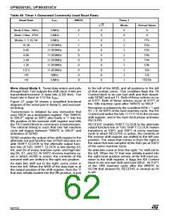
Using Timer 1 to Generate Baud Rates. When
Timer 1 is used as the baud rate generator, the
baud rates in Modes 1 and 3 are determined by
the Timer 1 overflow rate and the value of SMOD
as follows (see Table 45, page 62):
The timer can be configured for either “timer” or
“counter” operation. In the most typical applica-
tions, it is configured for “timer” operation (C/T2 =
0). “Timer” operation is a little different for Timer 2
when it’s being used as a baud rate generator.
Normally, as a timer it would increment every ma-
chine cycle (thus at the 1/6 the CPU clock frequen-
cy). In the case, the baud rate is given by the
formula:
Mode 1,3 Baud Rate =
SMOD
(2
/ 32) x (Timer 1 overflow rate)
Mode 1,3 Baud Rate = f
(RCAP2H, RCAP2L)]
/ (32 x [65536 -
OSC
The Timer 1 Interrupt should be disabled in this
application. The Timer itself can be configured for
either “timer” or “counter” operation, and in any of
its 3 running modes. In the most typical applica-
tions, it is configured for “timer” operation, in the
Auto-reload Mode (high nibble of TMOD = 0010B).
In that case the baud rate is given by the formula:
where (RCAP2H, RCAP2L) is the content of
RC2H and RC2L taken as a 16-bit unsigned inte-
ger.
Timer 2 also be used as the Baud Rate Generating
Mode. This mode is valid only if RCLK + TCLK = 1
in T2CON or in PCON.
Note: A roll-over in TH2 does not set TF2, and will
not generate an interrupt. Therefore, the Timer in-
terrupt does not have to be disabled when Timer 2
is in the Baud Rate Generator Mode.
Note: If EXEN2 is set, a 1-to-0 transition in T2EX
will set EXF2 but will not cause a reload from
(RCAP2H, RCAP2L) to (TH2, TL2). Thus when
Timer 2 is in use as a baud rate generator, T2EX
can be used as an extra external interrupt, if de-
sired.
It should be noted that when Timer 2 is running
(TR2 = 1) in “timer” function in the Baud Rate Gen-
erator Mode, one should not try to READ or
WRITE TH2 or TL2. Under these conditions the
timer is being incremented every state time, and
the results of a READ or WRITE may not be accu-
rate. The RC registers may be read, but should not
be written to, because a WRITE might overlap a
reload and cause WRITE and/or reload errors.
Turn the timer off (clear TR2) before accessing the
Timer 2 or RC registers, in this case.
Mode 1,3 Baud Rate =
SMOD
(2
/ 32) x (f
/ (12 x [256 – (TH1)]))
OSC
One can achieve very low baud rates with Timer 1
by leaving the Timer 1 Interrupt enabled, and con-
figuring the Timer to run as a 16-bit timer (high nib-
ble of TMOD = 0001B), and using the Timer 1
Interrupt to do a 16-bit software reload. Figure 22
lists various commonly used baud rates and how
they can be obtained from Timer 1.
Using Timer/Counter 2 to Generate Baud
Rates. In the uPSD321X Devices, Timer 2 select-
ed as the baud rate generator by setting TCLK
and/or RCLK (see Figure 22, page 53 Timer/
Counter 2 Control Register (T2CON)).
Note: The baud rate for transmit and receive can
be simultaneously different. Setting RCLK and/or
TCLK puts Timer into its Baud Rate Generator
Mode.
The RCLK and TCLK Bits in the T2CON register
configure UART 1. The RCLK1 and TCLK1 Bits in
the PCON register configure UART 2.
61/152

 STMICROELECTRONICS [ ST ]