UPSD3212C, UPSD3212CV
Mode 3. Timer 1 in Mode 3 simply holds its count.
The effect is the same as setting TR1 = 0.
Mode 3 is provided for applications requiring an
extra 8-bit timer on the counter. With Timer 0 in
Mode 3, an uPSD321X Devices can look like it has
three Timer/Counters. When Timer 0 is in Mode 3,
Timer 1 can be turned on and off by switching it out
of and into its own Mode 3, or can still be used by
the serial port as a baud rate generator, or in fact,
in any application not requiring an interrupt.
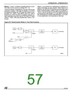
Timer 0 in Mode 3 establishes TL0 and TH0 as two
separate counters. The logic for Mode 3 on Timer
0 is shown in Figure 26. TL0 uses the Timer 0 con-
trol Bits: C/T, GATE, TR0, INT0, and TF0. TH0 is
locked into a timer function (counting machine cy-
cles) and takes over the use of TR1 and TF1 from
Timer 1. Thus, TH0 now controls the “Timer 1“ In-
terrupt.
Figure 26. Timer/Counter Mode 3: Two 8-bit Counters
f
÷ 12
OSC
C/T = 0
C/T = 1
TL0
(8 bits)
TF0
Interrupt
T0 pin
Control
TR0
Gate
INT0 pin
TH1
(8 bits)
f
TF1
Interrupt
÷ 12
OSC
Control
TR1
AI06624
57/152

 STMICROELECTRONICS [ ST ]