UPSD3212C, UPSD3212CV
POWER MANAGEMENT
All PSD MODULE offers configurable power sav-
ing options. These options may be used individu-
ally or in combinations, as follows:
■ The primary and secondary Flash memory, and
SRAM blocks are built with power management
technology. In addition to using special silicon
design methodology, power management
technology puts the memories into Standby
Mode when address/data inputs are not
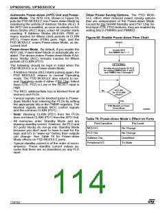
initiates Power-down Mode (if enabled). Once in
Power-down Mode, all address/data signals are
blocked from reaching memory and PLDs, and
the memories are deselected internally. This al-
lows the memory and PLDs to remain in
Standby Mode even if the address/data signals
are changing state externally (noise, other de-
vices on the MCU bus, etc.). Keep in mind that
any unblocked PLD input signals that are
changing states keeps the PLD out of Standby
Mode, but not the memories.
changing (zero DC current). As soon as a
transition occurs on an input, the affected
memory “wakes up,” changes and latches its
outputs, then goes back to standby. The
designer does not have to do anything special to
achieve Memory Standby Mode when no inputs
are changing—it happens automatically.
The PLD sections can also achieve Standby
Mode when its inputs are not changing, as de-
scribed in the sections on the Power Manage-
ment Mode Registers (PMMR).
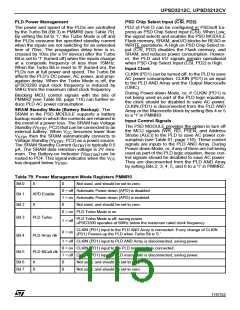
■ PSD Chip Select Input (CSI, PD2) can be used
to disable the internal memories, placing them
in Standby Mode even if inputs are changing.
This feature does not block any internal signals
or disable the PLDs. This is a good alternative
to using the APD Unit. There is a slight penalty
in memory access time when PSD Chip Select
Input (CSI, PD2) makes its initial transition from
deselected to selected.
■ The PMMRs can be written by the MCU at run-
time to manage power. The PSD MODULE
supports “blocking bits” in these registers that
are set to block designated signals from
reaching both PLDs. Current consumption of
the PLDs is directly related to the composite
frequency of the changes on their inputs (see
Figure 62 and Figure 63). Significant power
savings can be achieved by blocking signals
that are not used in DPLD or CPLD logic
equations.
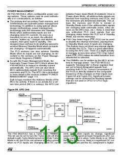
■ As with the Power Management Mode, the
Automatic Power Down (APD) block allows the
PSD MODULE to reduce to standby current
automatically. The APD Unit can also block
MCU address/data signals from reaching the
memories and PLDs. The APD Unit is described
in more detail in the sections entitled “POWER
MANAGEMENT” page 113.
Built in logic monitors the Address Strobe of the
MCU for activity. If there is no activity for a cer-
tain time period (MCU is asleep), the APD Unit
Figure 59. APD Unit
APD EN
PMMR0 BIT 1=1
TRANSITION
DETECTION
DISABLE BUS
INTERFACE
ALE
PD
CLR
APD
CSIOP SELECT
FLASH SELECT
COUNTER
RESET
EDGE
DETECT
PD
CSI
PLD
SRAM SELECT
POWER DOWN
CLKIN
(
)
PDN SELECT
DISABLE
FLASH/SRAM
AI06608
The PSD MODULE has a Turbo Bit in PMMR0.
This bit can be set to turn the Turbo Mode off (the
default is with Turbo Mode turned on). While Turbo
Mode is off, the PLDs can achieve standby current
when no PLD inputs are changing (zero DC cur-
rent). Even when inputs do change, significant
power can be saved at lower frequencies (AC cur-
rent), compared to when Turbo Mode is on. When
the Turbo Mode is on, there is a significant DC cur-
rent component and the AC component is higher.
113/152

 STMICROELECTRONICS [ ST ]