Electrical characteristics
ST10F276E
23.8.12 PLL lock/unlock
During normal operation, if the PLL is unlocked for any reason, an interrupt request to the
CPU is generated and the reference clock (oscillator) is automatically disconnected from the
PLL input: In this way, the PLL goes into free-running mode, providing the system with a
backup clock signal (free running frequency Ffree). This feature allows to recover from a
crystal failure occurrence without risking to go into an undefined configuration: The system
is provided with a clock allowing the execution of the PLL unlock interrupt routine in a safe
mode.
The path between the reference clock and PLL input can be restored only by a hardware
reset, or by a bidirectional software or watchdog reset event that forces the RSTIN pin low.
Note:
The external RC circuit on RSTIN pin must be the right size in order to extend the duration of
the low pulse to grant the PLL to be locked before the level at RSTIN pin is recognized high:
Bidirectional reset internally drives RSTIN pin low for just 1024 TCL (definitely not sufficient
to get the PLL locked starting from free-running mode).
Conditions: VDD = 5V 10%, TA = -40 / +125oC
Table 97. PLL lock/unlock timing
Value
Symbol
Parameter
Conditions
Unit
Min.
Max.
TPSUP
TLOCK
PLL Start-up time (1)
PLL Lock-in time
Stable VDD and reference clock
-
300
µs
Stable VDD and reference clock,
starting from free-running mode
-
250
Single Period Jitter (1)
(cycle to cycle = 2 TCL) (peak to peak)
6 sigma time period variation
TJIT
-500
+500
ps
Multiplication factors: 3, 4
Multiplication factors: 5, 8, 10, 16
PLL free running
frequency
250
500
2000
4000
Ffree
kHz
1. Not 100% tested, guaranteed by design characterization.
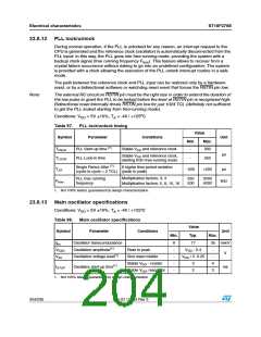
23.8.13 Main oscillator specifications
Conditions: VDD = 5V 10%, TA = -40 / +125°C
Table 98. Main oscillator specifications
Value
Typ.
Symbol
Parameter
Conditions
Unit
Min.
Max.
gm
Oscillator transconductance
Oscillation amplitude(1)
8
-
17
35 mA/V
VOSC
VAV
Peak to peak
VDD - 0.4
-
V
Oscillation-voltage level(1)
Sine wave middle
-
VDD / 2 -0.25
-
Stable VDD - crystal
Stable VDD, resonator
-
3
2
4
tSTUP
Oscillator start-up time(1)
ms
3
-
1. Not 100% tested, guaranteed by design characterization
204/235
Doc ID 12303 Rev 3

 STMICROELECTRONICS [ ST ]