Electrical characteristics
ST10F276E
2. Not 100% tested, guaranteed by design characterization.
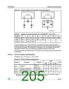
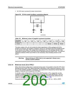
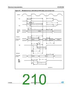
Figure 55. 32 kHz crystal oscillator connection diagram
34ꢀꢉ&ꢊꢄ%
#RYSTAL
#
#
!
!
'!0'2)ꢉꢉꢈꢈꢄ
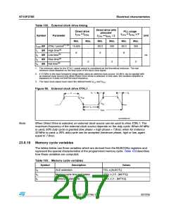
Table 101. Minimum values of negative resistance (module)
Oscillator
CA = 6pF CA = 12pF CA = 15pF CA = 18pF CA = 22pF CA = 27pF CA = 33pF
frequency
32 kHz
-
-
-
-
150 kΩ
120 kΩ
90 kΩ
The given values of CA do not include the stray capacitance of the package and of the
printed circuit board: The negative resistance values are calculated assuming additional 5pF
to the values in the table. The crystal shunt capacitance (C0), the package and the stray
capacitance between XTAL3 and XTAL4 pins is globally assumed equal to 4pF. The external
resistance between XTAL3 and XTAL4 is not necessary, since already present on the
silicon.
Warning: Direct driving on XTAL3 pin is not supported. Always use a
32 kHz crystal oscillator.
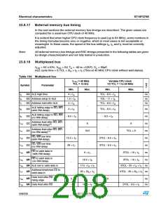
23.8.15 External clock drive XTAL1
When Direct Drive configuration is selected during reset, it is possible to drive the CPU clock
directly from the XTAL1 pin, without particular restrictions on the maximum frequency, since
the on-chip oscillator amplifier is bypassed. The speed limit is imposed by internal logic that
targets a maximum CPU frequency of 64 MHz.
In all other clock configurations (Direct Drive with Prescaler or PLL usage) the on-chip
oscillator amplifier is not bypassed, so it determines the input clock speed limit. Then an
external clock source can be used but limited in the range of frequencies defined for the
usage of crystal and resonator (refer also to Table 95 on page 199).
External clock drive timing conditions: VDD = 5V 10%, VSS = 0V, TA = -40 to +125°C
206/235
Doc ID 12303 Rev 3

 STMICROELECTRONICS [ ST ]