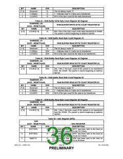
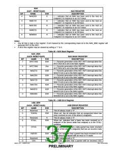
NAK
(0xD7 - RESET=0x00)
NAME
NAK REGISTER
DESCRIPTION
BIT
R/W
4
NAK2RX
R
1 = indicates that an NAK has been sent to the host on
Endpoint 2 in response to an OUT token.
3
2
1
0
NAK1TX
NAK1RX
NAK0TX
NAK0RX
R
R
R
R
1 = indicates that an NAK has been sent to the host on
Endpoint 1 in response to an IN token.
1 = indicates that an NAK has been sent to the host on
Endpoint 1 in response to an OUT token.
1 = indicates that an NAK has been sent to the host on
Endpoint 0 in response to an IN token.
1 = indicates that an NAK has been sent to the host on
Endpoint 0 in response to an OUT token.
Notes:
ꢀ
Any bit that is high in this register, if not masked by the corresponding mask bit in the NAK_MSK register will
generate INT5 to the 8051.
ꢀ
A bit in this register may be cleared by writing a “1” to it.
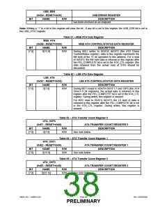
Table 49 – NAK Mask Register
NAK_MSK
(0xD9- RESET=0xFF)
NAME
NAK MASK REGISTER
DESCRIPTION
BIT
R/W
7
NYET2RX
R/W
1 = Prevents generation of the 8051 INT5 interrupt when the
NYET2RX bit is set in the NAK register.
6
5
4
3
2
1
0
NYET0RX
NAK2TX
NAK2RX
NAK1TX
NAK1RX
NAK0TX
NAK0RX
R/w
R/W
R/W
R/W
R/W
R/W
R/W
1 = Prevents generation of the 8051 INT5 interrupt when the
NYET0RX bit is set in the NAK register.
1 = Prevents generation of the 8051 INT5 interrupt when the
NAK2TX bit is set in the NAK register.
1 = Prevents generation of the 8051 INT5 interrupt when the
NAK2RX bit is set in the NAK register.
1 = Prevents generation of the 8051 INT5 interrupt when the
NAK1TX bit is set in the NAK register.
1 = Prevents generation of the 8051 INT5 interrupt when the
NAK1RX bit is set in the NAK register.
1 = Prevents generation of the 8051 INT5 interrupt when the
NAK0TX bit is set in the NAK register.
1 = Prevents generation of the 8051 INT5 interrupt when the
NAK0RX bit is set in the NAK register.
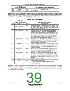
Table 50 – USB Error Register
USB_ERR
(0xDA - RESET=0x00)
NAME
USB ERROR REGISTER
DESCRIPTION
This bit always reads a “0”.
BIT
7
R/W
R
Reserved
6
TOKEN
R/W
When set, this bit indicates that an unexpected token has
been received on one of the device’s endpoints.
5
4
Reserved
STALL
R
This bit always reads a “0”.
R/W
When set, indicates that a token has been received on a
endpoint of the device while that endpoint is in the STALL
condition.
3
2
DTOG
R/W
R/W
When set, indicates that a data packet has been received
on one of the device’s endpoints that has an incorrect data
toggle.
RXERR
When set, indicates that a packet has been received on one
of the device’s endpoint with an error in FS mode.
1
0
Reserved
CRC
R
This bit always reads a “0”.
R/W
When set, indicates that a packet with an incorrect CRC
SMSC DS – USB97C201
Page 37
Rev. 03/25/2002
PRELIMINARY

 SMSC [ SMSC CORPORATION ]